Laser peening apparatus

a technology of laser peening and peening rod, which is applied in the direction of laser beam welding apparatus, welding apparatus, manufacturing tools, etc., can solve the problems of high volume of liquid for plasma trapping, workpiece required, contamination based on the type of liquid, etc., to prevent mass consumption of liquid, prevent corrosion and contamination, and save energy and convenien

Active Publication Date: 2008-05-08
SUBARU CORP +1
View PDF16 Cites 24 Cited by
  • Summary
  • Abstract
  • Description
  • Claims
  • Application Information

AI Technical Summary

Benefits of technology

[0014] It is, therefore, a main object of the present invention to provide a clean, energy saving and convenient laser peening apparatus which can prevent corrosion

Problems solved by technology

However, the above techniques have the following problems.
In the laser peening method in which the laser irradiation head and the workpiece are disposed in the water as described in Patent Document 3, there is a problem that a water tank which is large enough to accept an apparatus immersible portion such as the laser irradiation head and the workpiece is required.
Irrespective of water

Method used


Image

  • Laser peening apparatus
  • Laser peening apparatus

Examples


Embodiment Construction

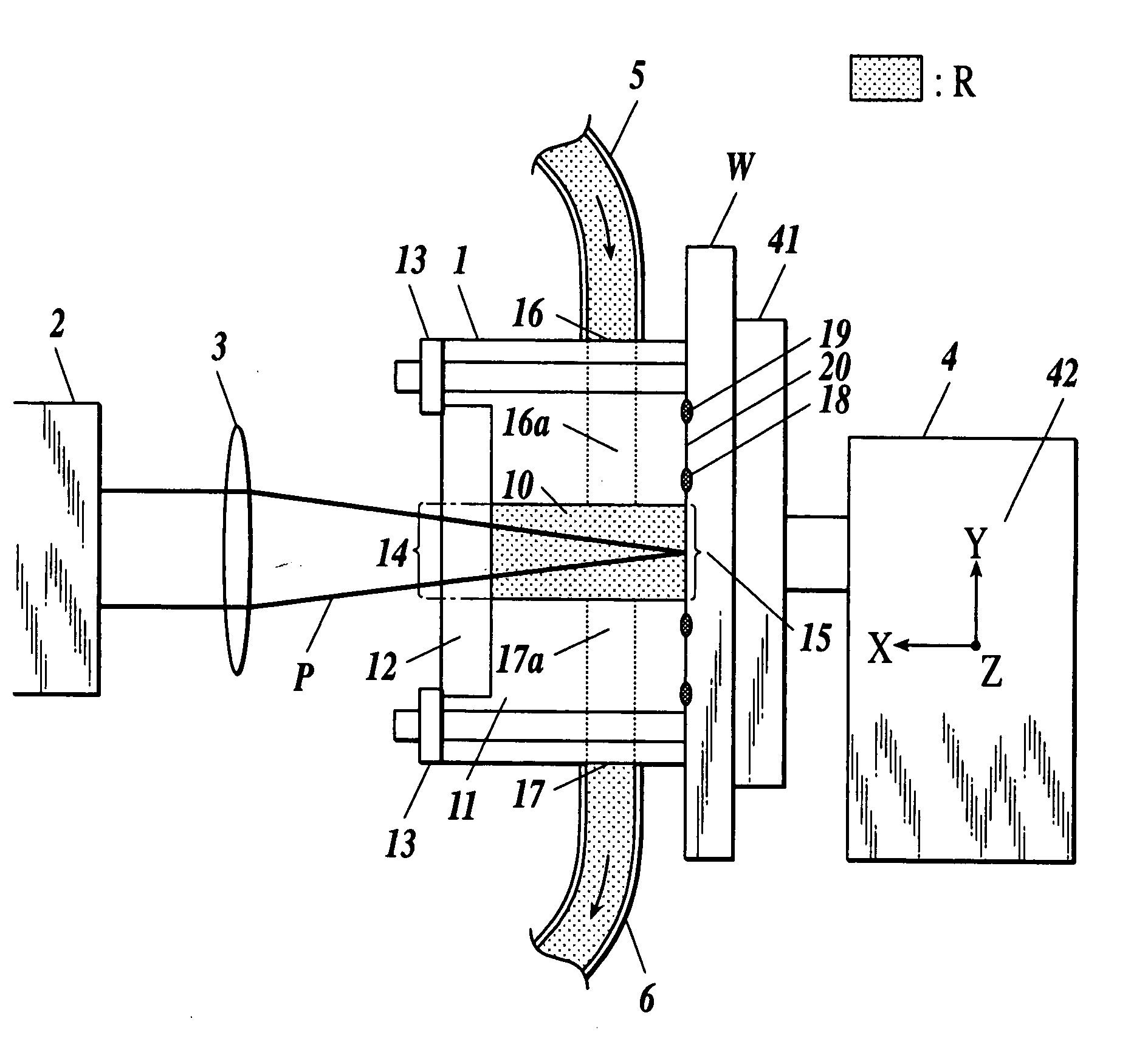
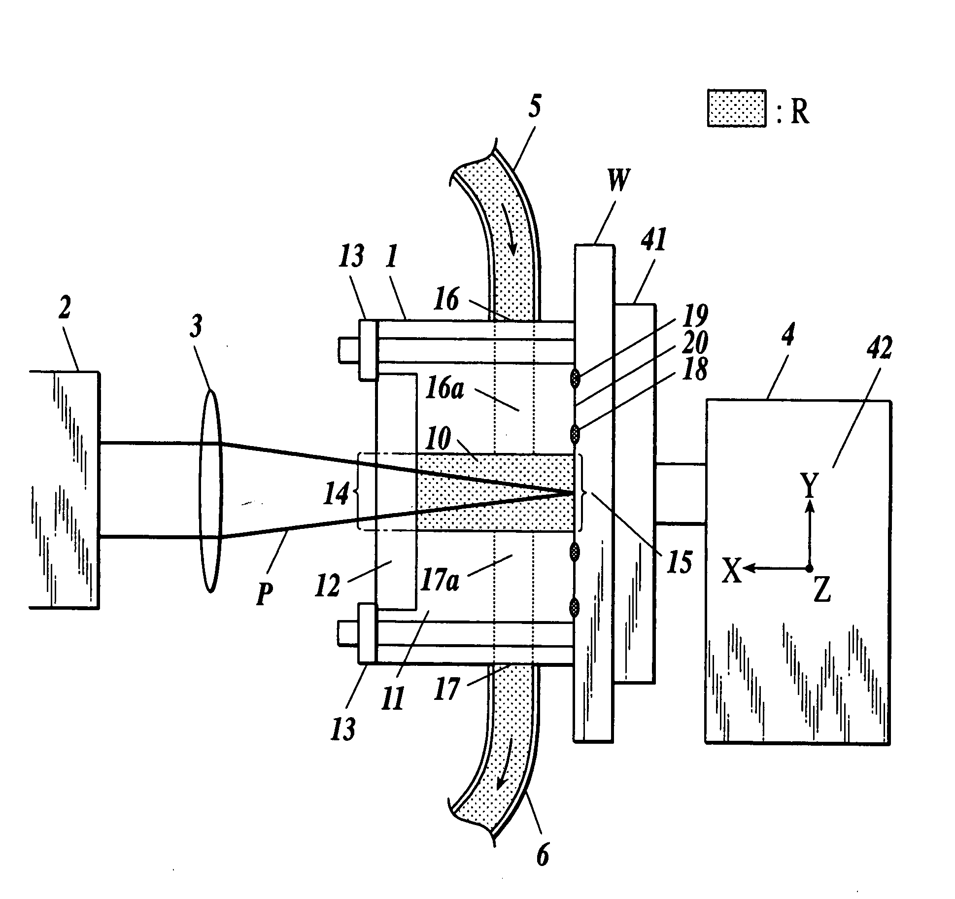
[0029] An embodiment of the present invention will be explained with reference to the drawing. The invention is not limited to the following embodiment of the invention. FIG. 1 is a sectional view of a laser peening apparatus according to the embodiment of the present invention.

[0030] As shown in FIG. 1, the laser peening apparatus of the embodiment includes a liquid holding head 1, a laser irradiation head 2, a condenser lens 3 and a workpiece moving device 4.

[0031] The liquid holding head 1 includes a sidewall body 11, a windowpane 12, glass retaining members 13 and O-rings 18 and 19.

[0032] The sidewall body 11 is a cylinder whose opposite ends are opened. The sidewall body 11 is made of metal or other material. A liquid holding chamber 10 is formed inside the sidewall body 11. One of the openings of the sidewall body 11 is an incident window 14 of the liquid holding chamber 10, and the other opening is an objective window 15 of the liquid holding chamber 10. The incident windo...


PUM

PropertyMeasurementUnit
Shapeaaaaaaaaaa

Abstract

Disclosed is a laser peening apparatus, including: a liquid holding head to shape and hold liquid to trap plasma on a local surface of a workpiece; and a laser irradiation head to irradiate the surface with laser through the liquid held in the liquid holding head.

Description

BACKGROUND OF THE INVENTION [0001] 1. Field of the Invention [0002] The present invention relates to a laser peening apparatus. [0003] 2. Description of Related Art [0004] As a method for giving a residual stress to a surface of a mechanical part or the like to reform the surface, a laser peening method is used. [0005] Generally, working by a laser peening method is carried out in such a manner that a to-be worked surface is irradiated with a laser beam in a focusing manner, generated plasma is trapped in liquid inertial medium such as water and oil formed on the to-be worked surface, and a shock wave pressure generated thereby is given to the to-be worked surface. To effectively give the shock wave pressure produced by plasma to the to-be worked surface, it is necessary to form liquid such as water and oil for trapping the plasma on the to-be worked surface. [0006] Japanese Patent Application Laid-open Publication No. 2000-246468 (hereinafter referred to as “Patent Document 1”) and...

Claims


Application Information

Patent Timeline
IPC IPC(8): B23K26/02B23K26/00B23K26/12B23K26/352C21D7/04
CPCB23K26/0069C21D10/005C21D7/06B23K26/121B23K26/1224B23K26/356
Inventor ADACHI, TAKAFUMIOGISU, TOSHIMICHI
Owner SUBARU CORP
Why Eureka
Try Eureka