
Biological implantation RFID tags and insertion jig therefor

a technology of biological implantation and rfid, which is applied in the field of biological implantation rfid (radio frequency identification) tags, can solve the problems of difficult to reduce the size and weight of biological elements, reducing their lifetime, and affecting the communication performance of the device, so as to achieve the effect of improving communication performan

Inactive Publication Date: 2008-05-08
HITACHI LTD
View PDF11 Cites 42 Cited by
  • Summary
  • Abstract
  • Description
  • Claims
  • Application Information

AI Technical Summary

Benefits of technology

[0008]Moreover, the above biological element (see the above prior art document) uses low-frequency radio signals to enable the communication between the implanted biological element and the living body. Thus, the antenna coil needs to be able to transmit and receive low-frequency radio signals, preventing the size and weight of the biological element from being reduced.
[0010]In view of the above problems, an object of the present invention is to provide a biological implantation RFID tag which can be subcutaneously implanted in a small animal without significantly stressing it and which exhibits improved communication performance, and an insertion jig used to implant the biological implantation RFID tag in the living body of a small animal.
[0014]The present invention can provide a biological implantation RFID (Radio Frequency IDentification) tag which can be subcutaneously implanted in a small animal without significantly stressing it and which exhibits improved communication performance, and an insertion jig used to implant the biological implantation RFID tag in the living body of a small animal.

Problems solved by technology

Consequently, implanting the RFID tag in the mouse significantly stresses the mouse, sharply reducing its lifetime.
Accordingly, it is difficult to reduce the size and weight of the biological element.
Furthermore, the cores of the glass capsule and antenna coil are not flexible.
This disadvantageously places significant stress on the small animal to sharply reduce its lifetime.
Thus, disadvantageously, if an electromagnetic wave of a high frequency, for example, a microwave band, is used for communication, a special reader antenna needs to be used instead of an ordinary tag reader antenna.
Further, such an electromagnetic wave provides only a short communication distance and a narrow reading area.

Method used


Image

  • Biological implantation RFID tags and insertion jig therefor
  • Biological implantation RFID tags and insertion jig therefor
  • Biological implantation RFID tags and insertion jig therefor

Examples


first embodiment

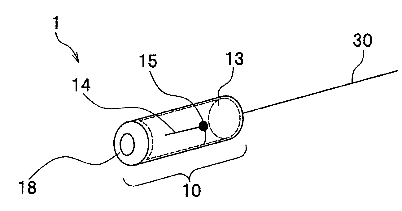
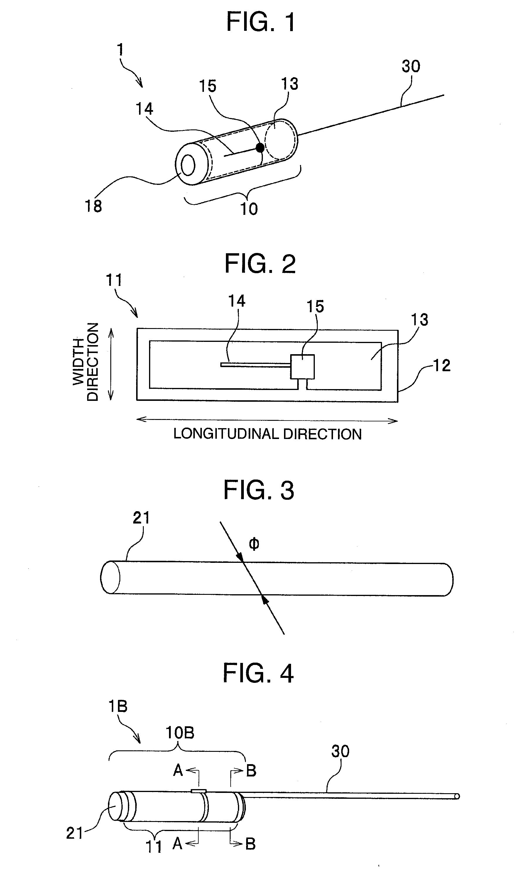
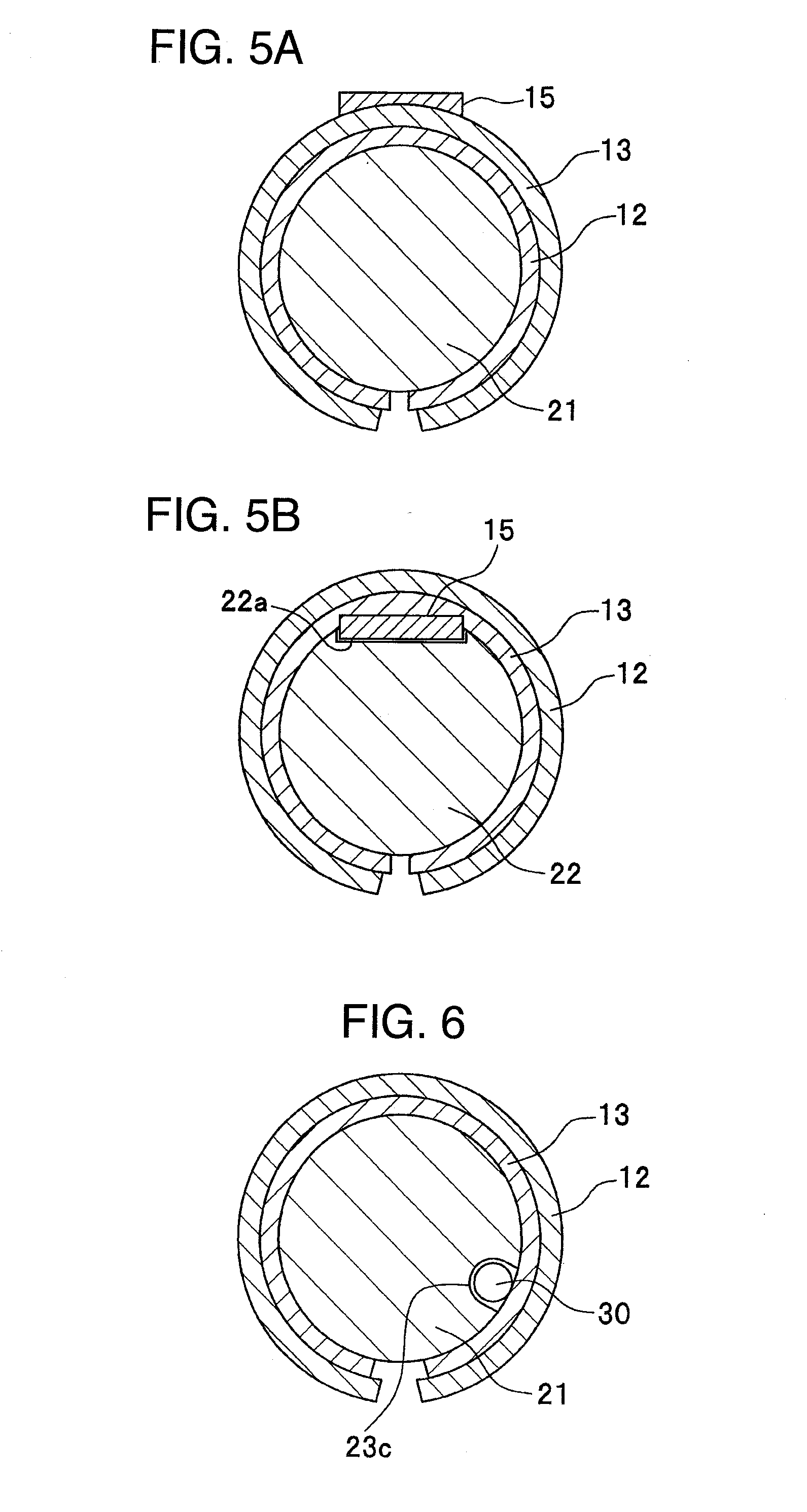
[0035]FIG. 1 is a diagram showing the structure of a biological implantation RFID tag 1 in accordance with a first embodiment of the present invention.

[0036]The biological implantation RFID tag 1 has an inlet portion 10 functioning as a biological implantation RFID tag and an auxiliary antenna 30 attached to the inlet portion 10. As described below, the entire inlet portion 10 of the biological implantation RFID tag 1 is subcutaneously implanted at a subcutaneous site (described below) of a small animal with all or a part of, preferably, most part of the auxiliary antenna 30 projected toward a free space outside the living body.

[0037]The biological implantation RFID tag 1 is subcutaneously implanted in a mouse or the like and is thus very small. However, the biological implantation RFID tag 1 can be implanted in other small or medium-size animals without posing any problem. The size of the biological implantation RFID tag 1 is such that its length is equal to at most 10% of the body...

second embodiment

[0082]FIG. 9 is a diagram showing the assembly of a biological implantation RFID tag 2 in accordance with a second embodiment of the present invention.

[0083]In the biological implantation RFID tag 2, a metal lead frame 60 provides the functions of both the main antenna 13 (see FIG. 2) and support 21 (see FIG. 3) of the biological implantation RFID tag 1 in accordance with the first embodiment.

[0084]As shown in FIG. 9A, the IC chip 15 is of a single-side electrode type and has two signal I / O electrodes 15a and 15b located on the same surface thereof.

[0085]As shown in FIG. 9B, the lead frame 60 has a slit 64 formed along the longitudinal direction, a main antenna 62 formed from one end to the center thereof, and a U-shaped stub 63 for impedance matching formed at the other end thereof. The main antenna 62 includes a caulking portion 60d (see FIG. 10) for connection with the auxiliary antenna 30 and connecting portions 60a and 60b for connection with the two signal I / O electrodes 15a a...

third embodiment

[0092]FIG. 11 is a diagram showing the assembly and configuration of a biological implantation RFID tag 3 in accordance with a third embodiment of the present invention.

[0093]The biological implantation RFID tag 3 in accordance with the third embodiment comprises an IC chip 16 of a double electrode type instead of comprising the IC chip 15 of a single electrode type in the biological implantation RFID tag 2 in accordance with the second embodiment. Further, the biological implantation RFID tag 3 in accordance with the third embodiment uses a lead frame 70 to provide the functions of both the main antenna 13 (see FIG. 2) and support 21 (see FIG. 3) of the biological implantation RFID tag 1 in accordance with the first embodiment, in almost the same manner as that in the second embodiment.

[0094]FIG. 11A is a perspective view of the IC chip 16. FIG. 11B is a side view of the IC chip 16.

[0095]The IC chip 16 is of a double electrode type and has a signal I / O electrode 16a formed on one s...


PUM


Abstract

The present invention provides a biological implantation RFID tag which can be subcutaneously implanted in a small animal without significantly stressing it and which exhibits improved communication performance, and an insertion jig used to implant the biological implantation RFID tag in the living body of a small animal. A biological implantation RFID tag is implanted in the living body of a small animal to transmit and receive an electromagnetic wave to and from the exterior of the living body to allow an ID assigned to the animal to be read. The biological implantation RFID tag includes an inlet having an IC chip that stores the ID and a main antenna, a support around which the inlet is wound to form an inlet portion, and an auxiliary antenna connected to the main antenna to extend it. Implanting the biological implantation RFID tag in the living body allows the inlet portion to be implanted in a subcutaneous tissue layer with most of the auxiliary antenna projecting out from the living body.

Description

INCORPORATION BY REFERENCE[0001]The present application claims priority from Japanese application JP2006-302075 filed on Nov. 7, 2006, the content of which is hereby incorporated by reference into this application.BACKGROUND OF THE INVENTION[0002]The present invention relates to biological implantation RFID (Radio Frequency IDentification) tags which can be subcutaneously implanted in small animals without significantly stressing them and which exhibit improved communication performance, and insertion jigs used to implant the biological implantation RFID tags in the living bodies of small animals.[0003]In recent years, RFID tags have been commonly used to label pets, domestic livestock, and experimental animals. The RFID tag includes an IC chip and an antenna and can transmit data such as an ID (IDentification: identifier) recorded in the IC chip, via an RF (Radio Frequency; high frequency) signal through the antenna. Thus, an RFID tag reader enables the ID data recorded in the IC c...

Claims


Application Information

Patent Timeline
IPC IPC(8): G08B1/08
CPCA61B17/06066A61B19/44G06K19/07749A61B2019/547A61B2019/5487A61B2019/448A61B90/90A61B90/98A61B2090/397A61B2090/3987G06K19/07A01K11/00H01Q1/24
Inventor SAKAMA, ISAOASHIZAWA, MINORUABE, HIROSHI
Owner HITACHI LTD
Learn More