Optical pickup lens

a pickup lens and optical technology, applied in the field of optical pickup lenses, can solve the problems of difficult to maintain good characteristics for both on-axis aberration, axis aberration, surface rb>2/b, etc., and achieve the effect of long working distance, good on-axis characteristic and off-axis characteristics

Active Publication Date: 2008-05-08
MAXELL HLDG LTD
View PDF3 Cites 22 Cited by
  • Summary
  • Abstract
  • Description
  • Claims
  • Application Information

AI Technical Summary

Benefits of technology

[0008]The present invention has been accomplished to solve the above problems and an object of the present invention is thus to provide an optical pickup lens with a high NA which maintains a longer working distance and has good on-axis characteristic and off-axis characteristics.

Problems solved by technology

However, if a numerical aperture NA exceeds 0.80, it is difficult to maintain good characteristics for both on-axis aberration such as spherical aberration and off-axis aberration such as astigmatic aberration and comatic aberration of a pickup lens.
Particularly, a biconvex lens in which a surface on the side close to a laser light source (surface R1) and a surface on the opposite side (surface R2) are both convex is difficult to have good angle of view characteristics.
The decrease in the working distance is particularly significant in a meniscus lens in which the surface R2 is not convex, thus increasing the risk of collision between an optical disc and an optical pickup lens.

Method used


Image

  • Optical pickup lens
  • Optical pickup lens
  • Optical pickup lens

Examples


Embodiment Construction

[0157]An embodiment of the present invention is described hereinafter in detail with reference to the drawings. In the following embodiment, the present invention is applied to an optical pickup lens used for recording or playing back information on an optical information recording medium.

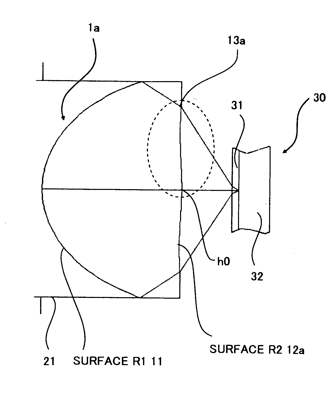
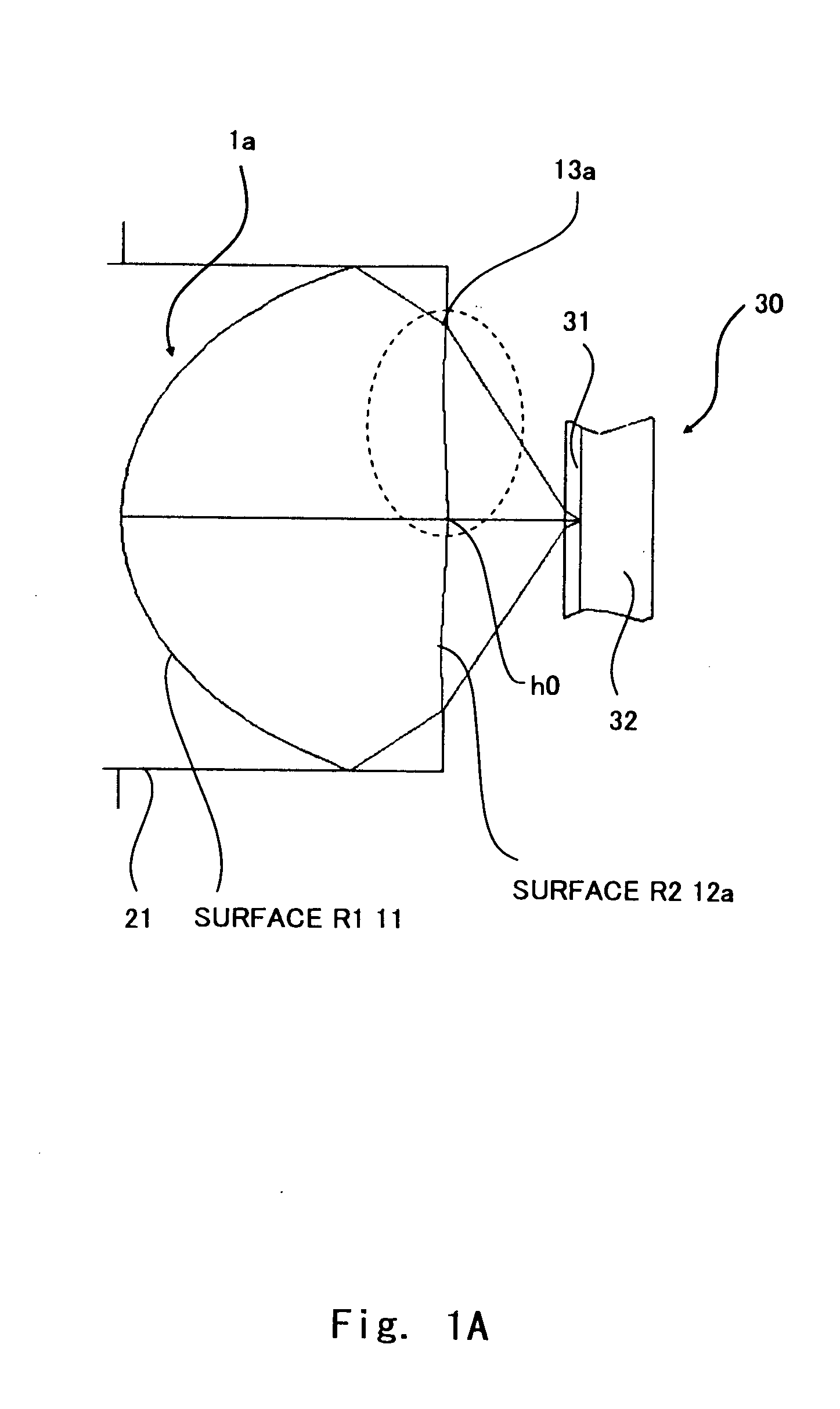
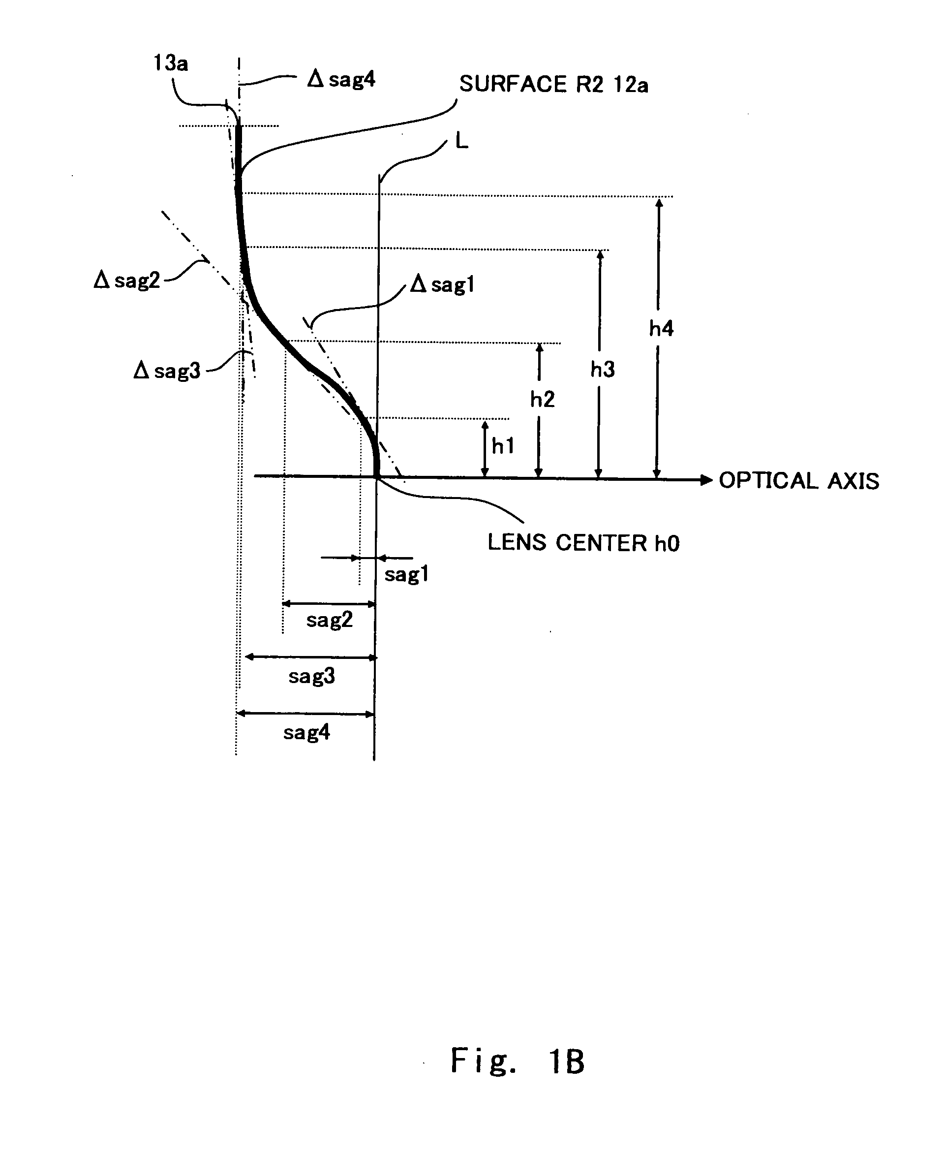
[0158]FIG. 1A is a view showing an optical pickup lens according to the embodiment of the present invention. FIG. 1B is a view to describe the sag of the optical pickup lens, which schematically shows a part within a dotted line in FIG. 1A in an enlarged scale. As shown in FIG. 1A, an optical pickup lens 1a, which is a single lens, of this embodiment has a first surface (which is referred to hereinafter as a surface R1) 11 that is closer to a laser light source and a second surface (hereinafter as a surface R2) 12a that is opposite to the first surface 11 and that faces an optical disc 30 which includes an optical disc substrate 32 and a light transmitting layer 31 in an optical disc. The surface R...


PUM

PropertyMeasurementUnit
thicknessaaaaaaaaaa
wavelengthaaaaaaaaaa
refractive indexaaaaaaaaaa

Abstract

An optical pickup lens for focusing a light beam from a laser light source on an optical information recording medium is a single lens. The optical pickup lens has two surfaces, and a surface R2 opposite to a surface R1 closer to the laser light source has a continuous shape. When the surface R2 has radii h1, h2 and h3 (h1<h2<h3) from an optical axis to a lens periphery, and where sags in the radii h1, h2 and h3 are sag1, sag2 and sag3, and differentials in the sags are Δsag1, Δsag2 and Δsag3, respectively, 0>Δsag1>Δsag2 and Δsag2<Δsag3 are satisfied.

Description

BACKGROUND OF THE INVENTION[0001]1. Field of the Invention[0002]The present invention relates to an optical pickup lens used in an optical system for performing recording or playback of an optical disc.[0003]2. Description of Related Art[0004]The recording capacity of an optical disc is ever increasing, and the recording density per unit area is also increasing. When reading information on an optical disc, light from a light source of an optical disc apparatus, after passing through an optical path including transparent components such as a wave plate and a collimator lens, is focused by an optical pickup lens to form an optical spot on an optical disc, thereby reading the information on the optical disc. Normally, light that is emitted from a laser light source enters an optical pickup lens after it is converted into parallel light by a collimator lens or the like. For an optical pickup lens which is used for reading a high-capacity optical disc, laser light with a wavelength of 41...

Claims


Application Information

Patent Timeline
Patent Type & Authority Applications(United States)
IPC IPC(8): G11B7/135
CPCG02B3/04G11B7/13922G11B7/1374
Inventor ITO, MITSURU
Owner MAXELL HLDG LTD
Why Eureka
Try Eureka