Infrared ndi for shallow defect detection

a defect detection and infrared technology, applied in the field of infrared ndi for shallow defect detection, can solve the problems of high training cost, high equipment cost, and inability to detect sub-surface flaws in structures, and the cost of infrared cameras and technicians trained to interpret thermographic displays

Inactive Publication Date: 2008-05-08
THE BOEING CO
View PDF36 Cites 25 Cited by
  • Summary
  • Abstract
  • Description
  • Claims
  • Application Information

AI Technical Summary

Problems solved by technology

Inspections may also be prompted by incidents such as collisions and ballistic impacts.
NDI methods that include infrared imaging are available but involve costly equipment and a high degree of training.
Such a display can reveal, to the trained eye, sub-surface flaws in a structure.
However, the necessary infrared cameras and technicians trained to interpret thermographic displays represent considerable costs.
Thus, while the equipment and experience needed for infrared imaging may be available at specialized repair and maintenance facilities, they are not typically readily available at commercial airports and remote aviation facilities.
Incidents of minor and superficial damages are expected at busy aviation facilities.
Commercial aircraft encounter airborne debris in-flight and are subject to inadvertent collisions from luggage loaders and passenger loading ramps.
Military aircraft are subject to damages from ballistic weapons and shrapnel.
Other marks overlay sub-surface damages that can threaten the integrity of the marked component.
Crews that fuel, load, and generally prepare airplanes for flight face a critical challenge.
Sub-surface damages to aircraft components typically begin at the skins of the components.
Damages can propagate inward through a component-skin such that an incident which threatens the structural integrity of a component leaves only a small marking at the surface where an impact occurred.
Exterior repair patches can also overlay sub-surface problems.
For example, a surface-applied patch can be poorly bonded or can overlay backing material inadvertently sandwiched between the patch and a surface.

Method used


Image

  • Infrared ndi for shallow defect detection
  • Infrared ndi for shallow defect detection
  • Infrared ndi for shallow defect detection

Examples


Embodiment Construction

[0018]One or more embodiments of the present invention now will be described more fully hereinafter with reference to the accompanying drawings, in which some, but not all embodiments of the invention are shown. Indeed, the invention may be embodied in many different forms and should not be construed as limited to the embodiments set forth herein; rather, these embodiments are provided so that this disclosure will satisfy applicable legal requirements. Like numbers refer to like elements throughout.

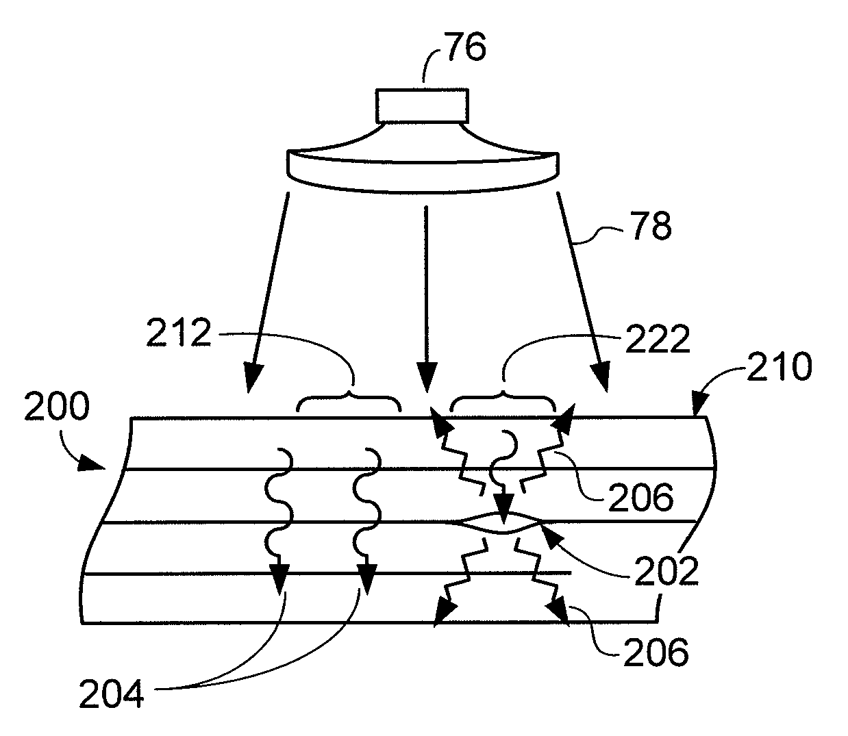
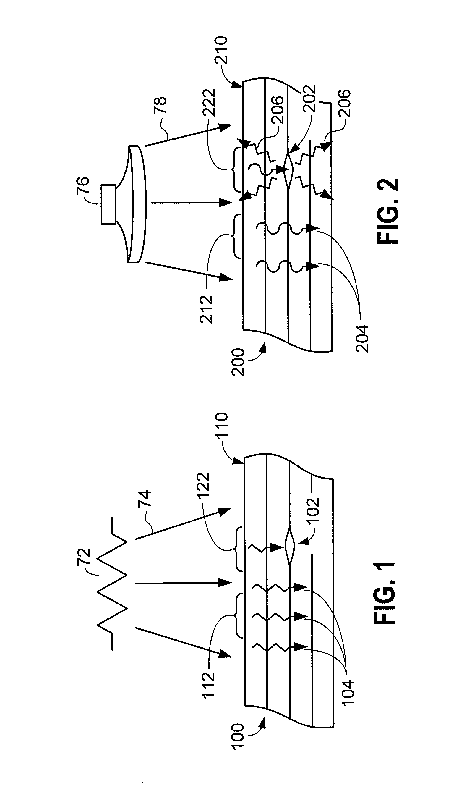
[0019]A theoretical approach to understanding the flow of heat into a structure, the production of heat within a structure in response to incident energy such as ultrasonic energy, and the production of temperature gradients on the surface of a structure by which sub-surface defects may be detected are described herein with references to FIGS. 1-2. Such descriptions are provided to promote an understanding of concepts underlying the developments of various embodiments of the invention. Em...


PUM

PropertyMeasurementUnit
diameteraaaaaaaaaa
diameteraaaaaaaaaa
diametersaaaaaaaaaa

Abstract

First and second thermal sensors measure the respective temperatures of portions of a surface of a structure such as an aircraft component. An alert signal is emitted if the temperatures of the surface portions are substantially different. An energy source causes heat flow within the structure. Subsurface flaws such as disbonded areas between composite layers and foreign materials obstruct heat flow within the structure and cause proximate surface portions to exhibit different temperatures. A non-alert signal may be emitted if the temperatures of proximate surface portions are essentially the same.

Description

FIELD OF THE INVENTION[0001]Embodiments of the present invention relate generally to non-destructive devices and methods for inspecting structures. More particularly, embodiments of the invention relate to devices and methods for inspecting a skin of a structure for the presence of shallow sub-surface flaws, damages, and trapped foreign matter.BACKGROUND OF THE INVENTION[0002]Non-destructive inspection (NDI) of structures involves examining a structure without harming the structure or requiring significant disassembly. NDI methods are often preferred in order to avoid the time and costs associated with the removal of a part and to avoid the potential for causing damages when inspection is needed. In some situations, NDI methods might be the only methods by which inspections may be performed. NDI devices and methods are used in the aircraft industry to inspect aircraft structures such as composite structures and bonded panels. Inspections may identify defects such as cracks, disconti...

Claims


Application Information

Patent Timeline
Patent Type & Authority Applications(United States)
IPC IPC(8): G01N25/72
CPCG01N25/72B64F5/60G01N21/88
Inventor KOLLGAARD, JEFFREY R.THOMPSON, JEFFREY G.UYEHARA, CLYDE T.
Owner THE BOEING CO
Why Eureka
Try Eureka