Fan fixing apparatus

a technology for fixing apparatuses and fans, which is applied in mechanical apparatuses, electrical apparatus construction details, couplings, etc., can solve the problems of increasing the internal temperature of the casing gradually, increasing the power consumption and heating power of electronic elements, and discharging thermal energy, so as to achieve stable positioning on the casing and avoid too many complicated assembling parts

Inactive Publication Date: 2008-05-08
INVENTEC CORP
View PDF17 Cites 26 Cited by
  • Summary
  • Abstract
  • Description
  • Claims
  • Application Information

AI Technical Summary

Benefits of technology

[0011]Accordingly, the problem to be solved by the present invention is to provide a fan fixing apparatus which can be stably positioned on the casing without using the assistant tool, and without too many complicated assembling parts.
[0014]In order to enhance the positioning effect of the fan fixing apparatus, a snapping module may be added on the whole apparatus. A supporting block is disposed on the casing, and a snapping member is disposed on the surface of the frame facing the supporting block. When the frame finishes the positioning action, the snapping member is snapped with the supporting block, thereby forming the force for keeping the mushroom pillar be positioned in the positioning portion, so as to enhance the positioning effect of the frame.
[0016](1) The replacement of the fan is easier and more convenient. In the conventional art, the screwing or buckling manner is used for fixing, and usually the assistant tool is required, for example the screw driver is required by the screw latching, such that the assembling or disassembling operation of the fan is quite time consuming and painstaking. However, with the fan fixing apparatus of the present invention, it is only required to insert the mushroom pillars into the gourd holes, and move them to the positioning portions, thus finishing the position of the frame. The snapping module may be further added to keep the mushroom pillar be positioned by the force generated by snapping, so it is more convenient than the conventional art.
[0017](2) The time cost is saved. In the conventional art, when the fan is fixed, usually additional parts, such as the fan supporting frame or the outer frame mask are required to be assembled to assist fixing the fan. However, the fan fixing apparatus of the present invention does not need to assemble the complicated parts, and all the functions of the components may be easily known from the appearance, so as to perform positioning. Even if the adding of the snapping module only needs a snapping action additionally to finish the positioning of the fan fixing apparatus, therefore, the time for the user to recognize the function of the element and to assemble the element is significantly saved.

Problems solved by technology

No matter what kinds of electronic equipments or computer equipments, a same problem, i.e., dissipation of the thermal energy, exists during booting and operation.
Correspondingly, the internal functional circuits of the electronic elements, such as the processing chip, contained in the casing of the equipment increase, so the power consumption and the heating power of the electronic elements increase correspondingly, thus the internal temperature of the casing gradually increases.
However, the overhigh temperature may affect the normal operation of the electronic elements, and more seriously, the electronic elements may be burnt.
(1) It is difficult to replace. If the screwing manner is used to fix the fan, no matter when the fan itself or the fixing apparatus is disposed or disassembled, the assistant tools are required, such as screw driver or wrench, so as to screw or unscrew the screws used for fixing. If the fan fails and the tool does not exist, it is impossible to perform the disassembling operation to replace a new fan. Next, for the buckling structure, the buckling hooks are usually fixed on the buckling holes by fluke buckling, and additionally tools are required for assisting during disassembling. If the assistant tools are not used, usually the buckling structure is destroyed due to incorrect manner of force application.
(2) The assembling parts are complicated. No matter for the screwing manner or the buckling manner, assembling a single fan or using the fixing apparatus to assist the positioning of the fan, a plurality of parts is required for the fixing operation. For example, the screwing manner needs a plurality of screws or cap nuts, and according to different situations, the parts such as the fan supporting frame or the outer frame mask are required for assisting positioning. The recognition of the function of the parts spends a lot of time, and performing assembling operation with various kinds of parts may spend more. Moreover, if a part is not assembled, the fan is not fixed firmly enough, thus resulting in the displacement situation.

Method used


Image

  • Fan fixing apparatus
  • Fan fixing apparatus
  • Fan fixing apparatus

Examples


Embodiment Construction

[0032]In order to make a further understanding of the object, the construction feature and the function of the present invention, it is described with the relative embodiments and the drawings as follows.

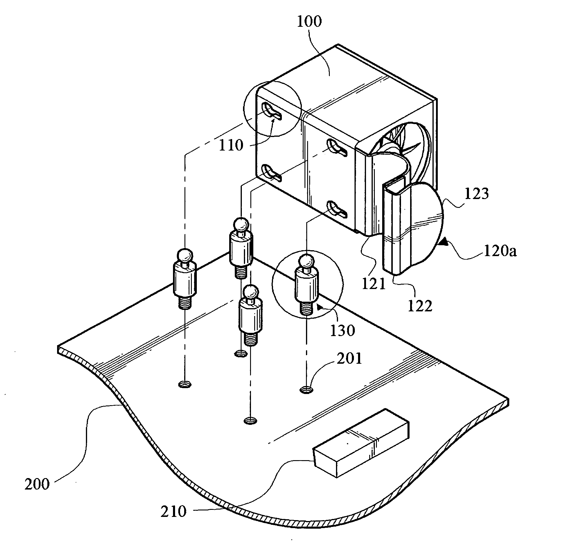
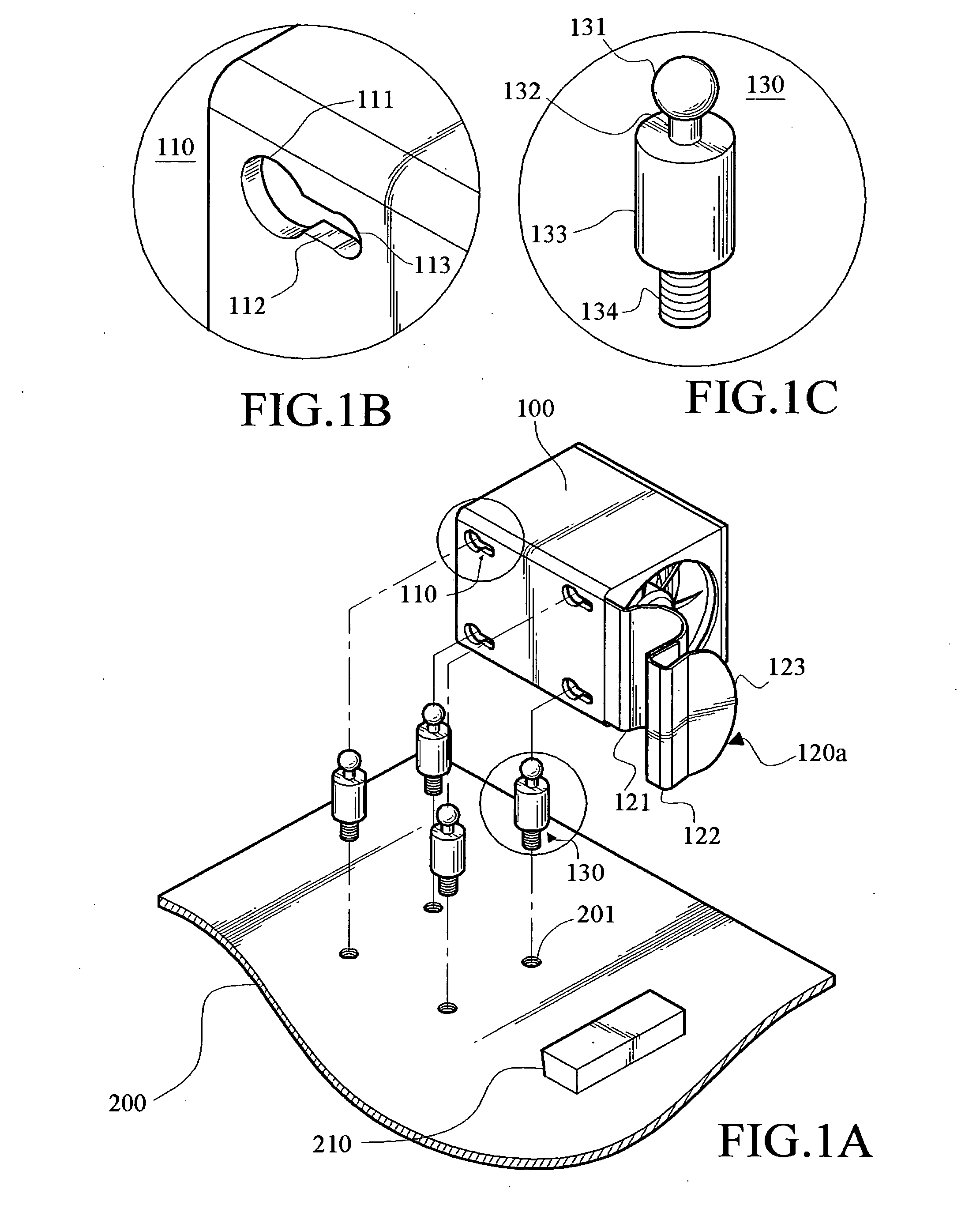
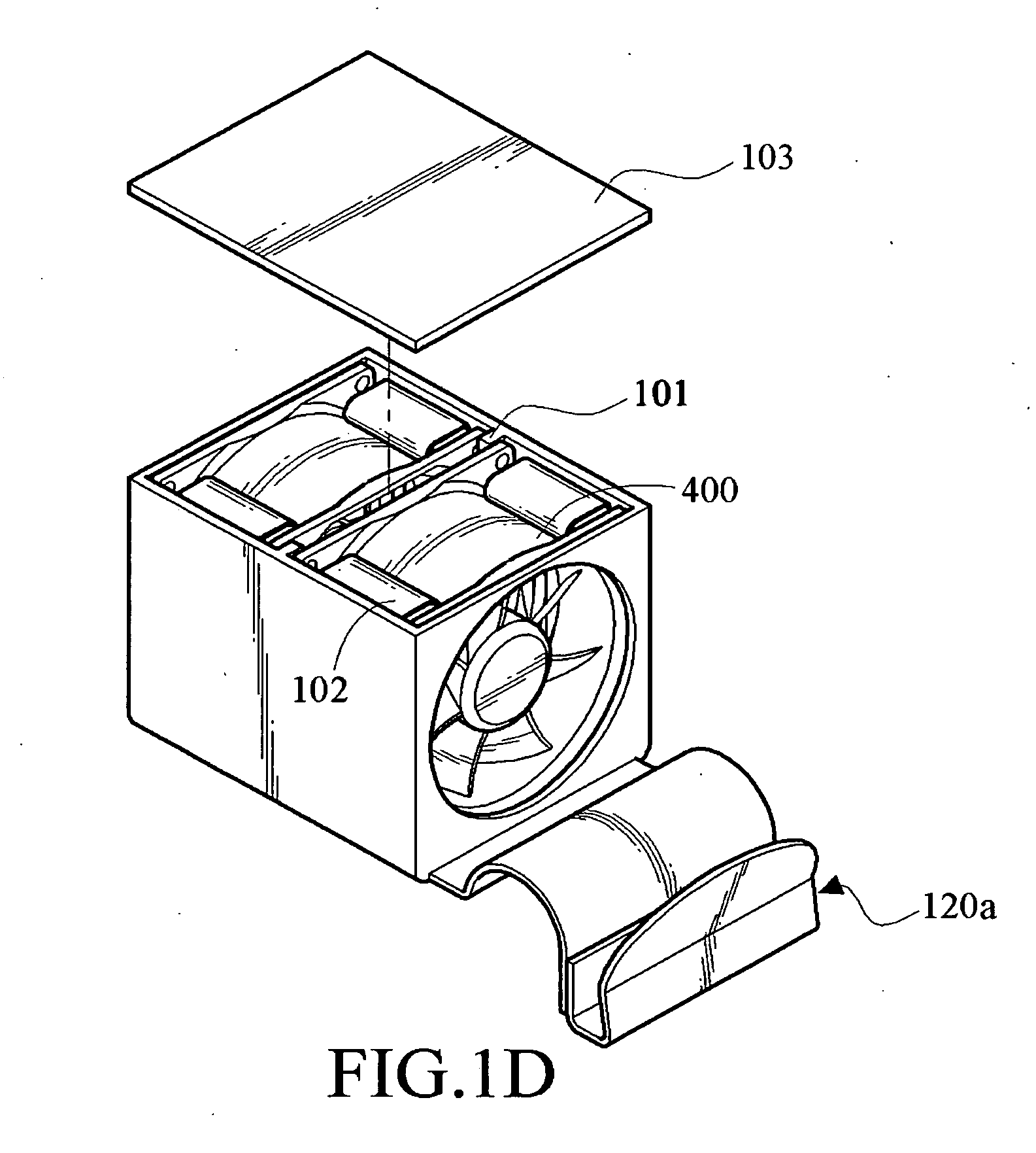
[0033]As shown in FIGS. 1A to 1D, the structural view of the fan fixing apparatus and the detailed views of part of the elements of the present invention are shown. The fan fixing apparatus includes a frame 100, a snapping member 120a, a plurality of mushroom pillars 130 and a supporting block A 210. The frame 100 has a clamping portion (formed by a spacing strip 101 and an elastic clamping piece 102) for clamping the fan 400. The spacing strip 101 is used to separate the inner space of the frame 100 to form a plurality of accommodation slots, and the elastic clamping piece 102 is used to clamp and fix the fan 400 in the accommodation slot, and the top cover 103 is shut to seal the opening of the frame 100, so as to finish the fan clamping operation. However, the fan 400 clamped by ...


PUM


Abstract

A fan fixing apparatus is provided. The fan fixing apparatus clamps the fan and positions the fan on the casing. The fan fixing apparatus includes a plurality of mushroom pillars and a frame. The mushroom pillars are disposed on the casing, and the frame has a clamping portion for clamping the fan and a plurality of gourd holes corresponding to the mushroom pillars. The gourd hole has a guiding portion, a positioning portion and a slide rail communicating the guiding portion and the positioning portion. The mushroom pillar is inserted into the guiding portion, and is finally positioned in the positioning hole by moving along the slide rail, such that the fan fixing apparatus is rapidly positioned in the casing.

Description

BACKGROUND OF THE INVENTION[0001]1. Field of Invention[0002]The present invention relates to a fan fixing apparatus. More particularly, the present invention relates to a fixing apparatus capable of positioning the fan on the casing rapidly by using the relative displacement between the mushroom pillars and the gourd holes.[0003]2. Related Art[0004]No matter what kinds of electronic equipments or computer equipments, a same problem, i.e., dissipation of the thermal energy, exists during booting and operation. As people seek for the convenience in using, the necessary functions and the achievable performance required by the equipment itself are increasingly improved. Correspondingly, the internal functional circuits of the electronic elements, such as the processing chip, contained in the casing of the equipment increase, so the power consumption and the heating power of the electronic elements increase correspondingly, thus the internal temperature of the casing gradually increases....

Claims


Application Information

Patent Timeline
Patent Type & Authority Applications(United States)
IPC IPC(8): F16J1/16
CPCF16B21/09Y10T403/32901H05K7/20172
Inventor YANG, CHUN-YU
Owner INVENTEC CORP
Why Eureka
Try Eureka