
Methods and apparatus for carrier-free deflection electrophoresis

a carrier-free deflection and electrophoresis technology, applied in the direction of liquid/fluent solid measurement, process and machine control, peptides, etc., can solve the problem of reducing the diffusion rate of analytes, unable to prevent the negative influence of the laminar flow profile for low-molecular analytes, and increasing the viscosity. problems, to achieve the effect of reducing the influence of the laminar flow profile, reducing the turn around time and reducing th

Inactive Publication Date: 2008-05-15
BECTON DICKINSON & CO
View PDF73 Cites 7 Cited by
  • Summary
  • Abstract
  • Description
  • Claims
  • Application Information

AI Technical Summary

Benefits of technology

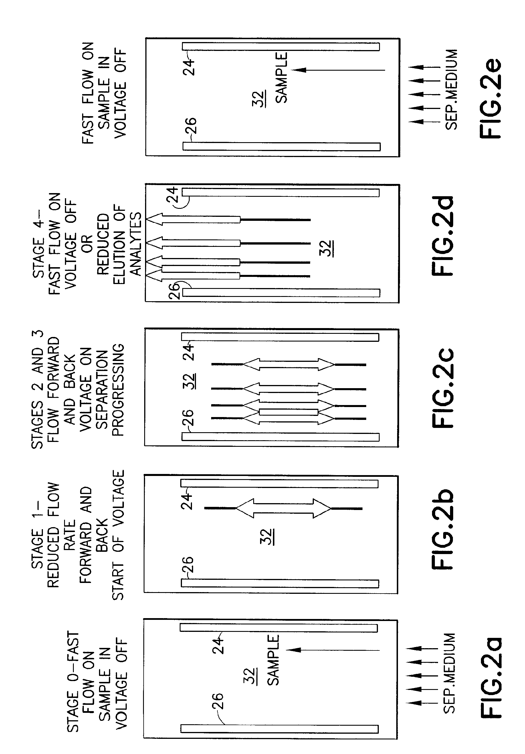
[0025]Accordingly, the object of the invention is to provide a method for carrier-free deflection electrophoresis, which eliminates the influence of a laminar flow profile typical of continuous free-flow electrophoretic separations and additionally increases separation quality and / or reducing the turn around time or reduction in fractionation time needed to obtain high resolution quality for electrophoretic separations. The method and device of the present invention can be used for both preparative and analytical separations.

Problems solved by technology

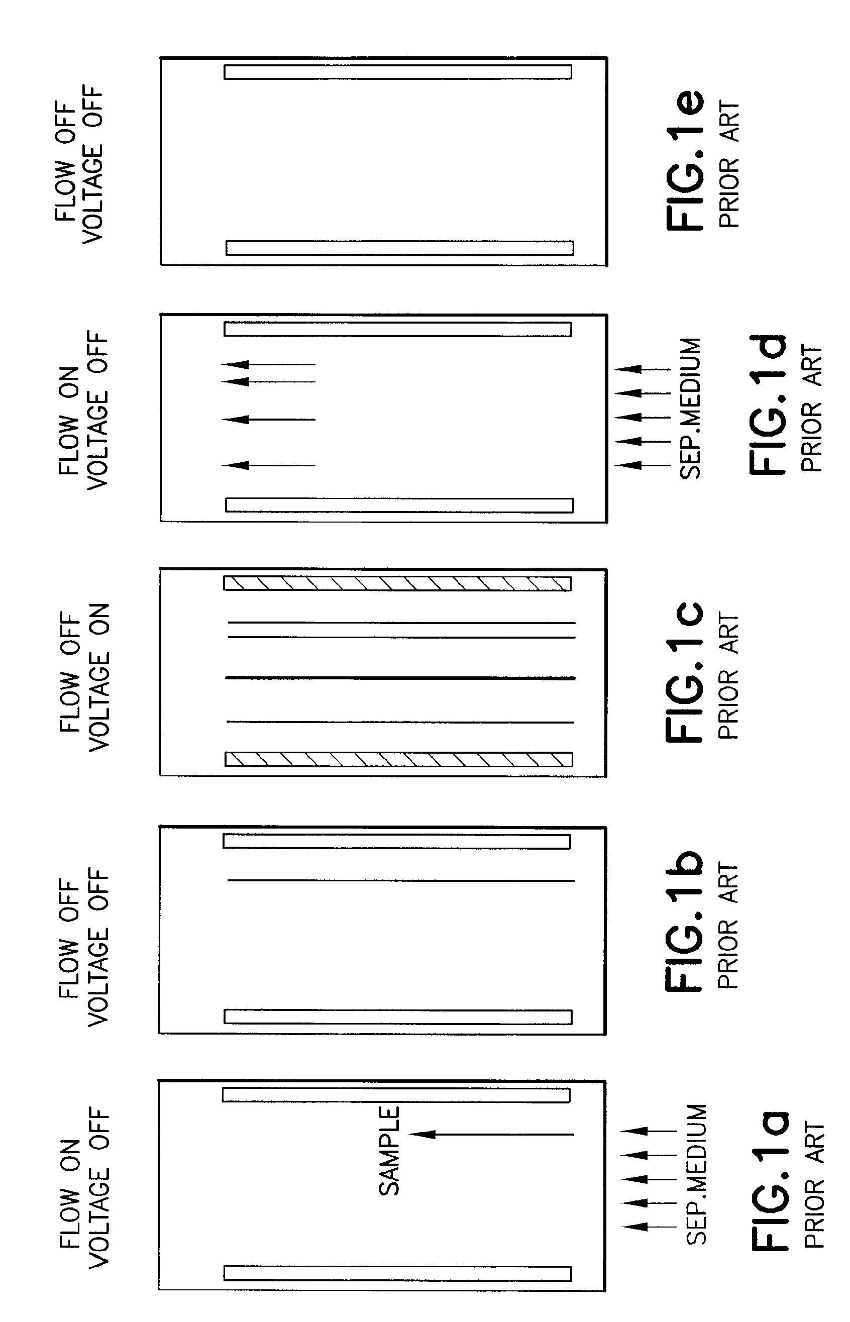
Given a continuously executed electromigration process under the boundary conditions of carrier-free electrophoresis, the negative influence of the laminar flow profile cannot be averted for low-molecular analytes.
Reducing the diffusion rates for analytes that have their migration impacted by using separation media with increased viscosity also does not help, since this magnifies the unfavorable nature of the laminar flow profile.
However, the influence of laminar flow profile can only be minimized in this way by distinctly reducing the sample feeding rate (e.g., to a sample flow rate that is only 0.1% to 0.5% of the flow rate of the separation medium).

Method used


Image

  • Methods and apparatus for carrier-free deflection electrophoresis
  • Methods and apparatus for carrier-free deflection electrophoresis
  • Methods and apparatus for carrier-free deflection electrophoresis

Examples


Embodiment Construction

[0054]The present invention and its advantages are further illustrated in the following, non-limiting examples. In the drawings, like reference characters generally refer to the same parts throughout the different views. Also, the drawings are not necessarily to scale, emphasis instead being placed upon illustrating the principles of the invention.

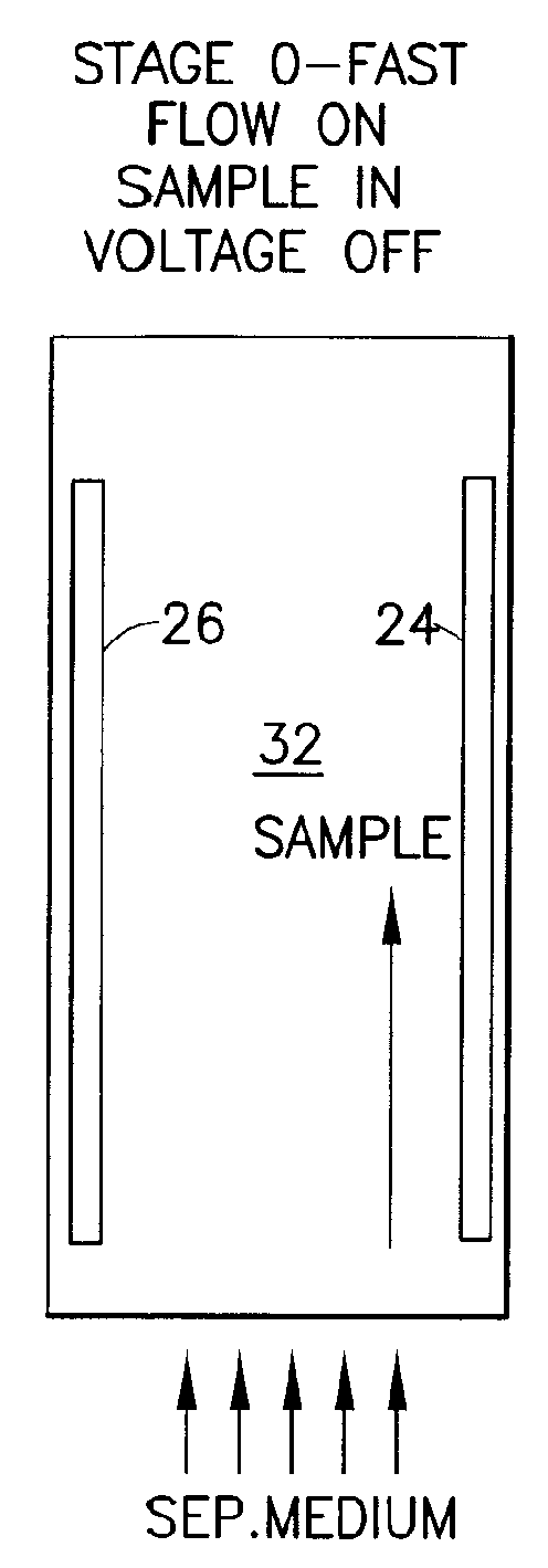
[0055]The general method of the present invention is reflected in FIG. 2 (specifically FIGS. 2a-2e) while the elements typically required for carrying out the invention are collectively described in FIGS. 3, 4, 7a, and 8a. Reflected schematically in FIGS. 3 and 4 are two embodiments of an electrophoresis apparatus 10 including an electrophoresis chamber 12 as well as elements relating to and / or connected to the electrophoresis chamber 12, while FIGS. 7a and 8a reflect specifically the electrophoresis chamber 12 as well as the electrophoretic behavior of the particles as schematically represented in the electrophoresis chamber 12.

[0056]An a...


PUM

PropertyMeasurementUnit
Thicknessaaaaaaaaaa
Flow rateaaaaaaaaaa
Currentaaaaaaaaaa

Abstract

The invention relates to a method and apparatus for carrier-free deflection electrophoresis, in which a separating media and a sample to be examined flow through a separating chamber between a pair of electrodes in a series of reversing bulk fluid flow along the direction of the electrodes, thereby separating the sample into zones which are to be collected into fractions for analysis or further processing. Among other things, the apparatus and method enable high-resolution separation of particles that can be performed in miniaturized chambers in electrophoresis modes including isoelectric focusing, zone electrophoresis, and isotachophoresis.

Description

[0001]This patent application claims priority to U.S. Provisional Patent Application Ser. No. 60 / 823,833 filed on Aug. 29, 2006 and U.S. Provisional Patent Application Ser. No. 60 / 883,260 filed on Jan. 3, 2007.FIELD OF THE INVENTION[0002]The invention relates to carrier-free deflection electrophoresis, including an apparatus and method for carrying out the same.BACKGROUND OF THE INVENTION[0003]The basics of carrier-free deflection electrophoresis, especially with respect to continuously operated processes, have been described in the literature over 30 years ago. The process is sometimes described under the term FFE (free flow electrophoresis) or more commonly CFE (continuous flow electrophoresis). (K. Hannig: Carrier-free continuous electrophoresis and its application. Anal. Chem. 181, 233 (1961); M. C. Roman and P. R. Brown: Anal. Chem. Free Flow Electrophoresis. 66(N2), 86-94, (1994); R. Braun, H. Wagner and G. Weber: Preparative Free Flow Electrophoresis—a powerful procedure for ...

Claims


Application Information

Patent Timeline
IPC IPC(8): B01D57/02C02F1/469G05B21/02
CPCG01N27/44795G01N27/44769
Inventor WEBER, GERHARD
Owner BECTON DICKINSON & CO
Learn More