Digital calibration circuits, devices and systems including same, and methods of operation

a digital calibration and circuit technology, applied in the field of integrated circuits, can solve problems such as excessive over-compensation, output drivers over-shoot or under-shoot desired signal levels, and reduce timing and voltage margins that affect signal integrity

Active Publication Date: 2008-05-15
MICRON TECH INC
View PDF56 Cites 41 Cited by
  • Summary
  • Abstract
  • Description
  • Claims
  • Application Information

AI Technical Summary

Problems solved by technology

Variations in process, voltage, temperature and other factors may cause the output drivers to overshoot or undershoot desired signal levels.
Consequently, the impedance mismatch of the output driver results in reduced timing and voltage margins that impact signal integrity.
Another problem associated with the conventional calibration circuit 100 is that excessive over-compensation may occur as the binary searcher 140 iteratively adjusts the adjustment signal PADJ by a particular step size that may be larger than the difference in magnitude of ZQ and VREF.
Additionally, the binary searcher 140 may be forced

Method used


Image

  • Digital calibration circuits, devices and systems including same, and methods of operation
  • Digital calibration circuits, devices and systems including same, and methods of operation
  • Digital calibration circuits, devices and systems including same, and methods of operation

Examples


Embodiment Construction

[0022]Embodiments of the present invention are directed to circuits providing adjustments to match the impedance of an externally accessible output terminal. Certain details are set forth below to provide a sufficient understanding of the invention. However, it will be clear to one skilled in the art that the invention may be practiced without these particular details. In other instances, well-known circuits, control signals, and timing protocols have not been shown in detail in order to avoid unnecessarily obscuring the invention.

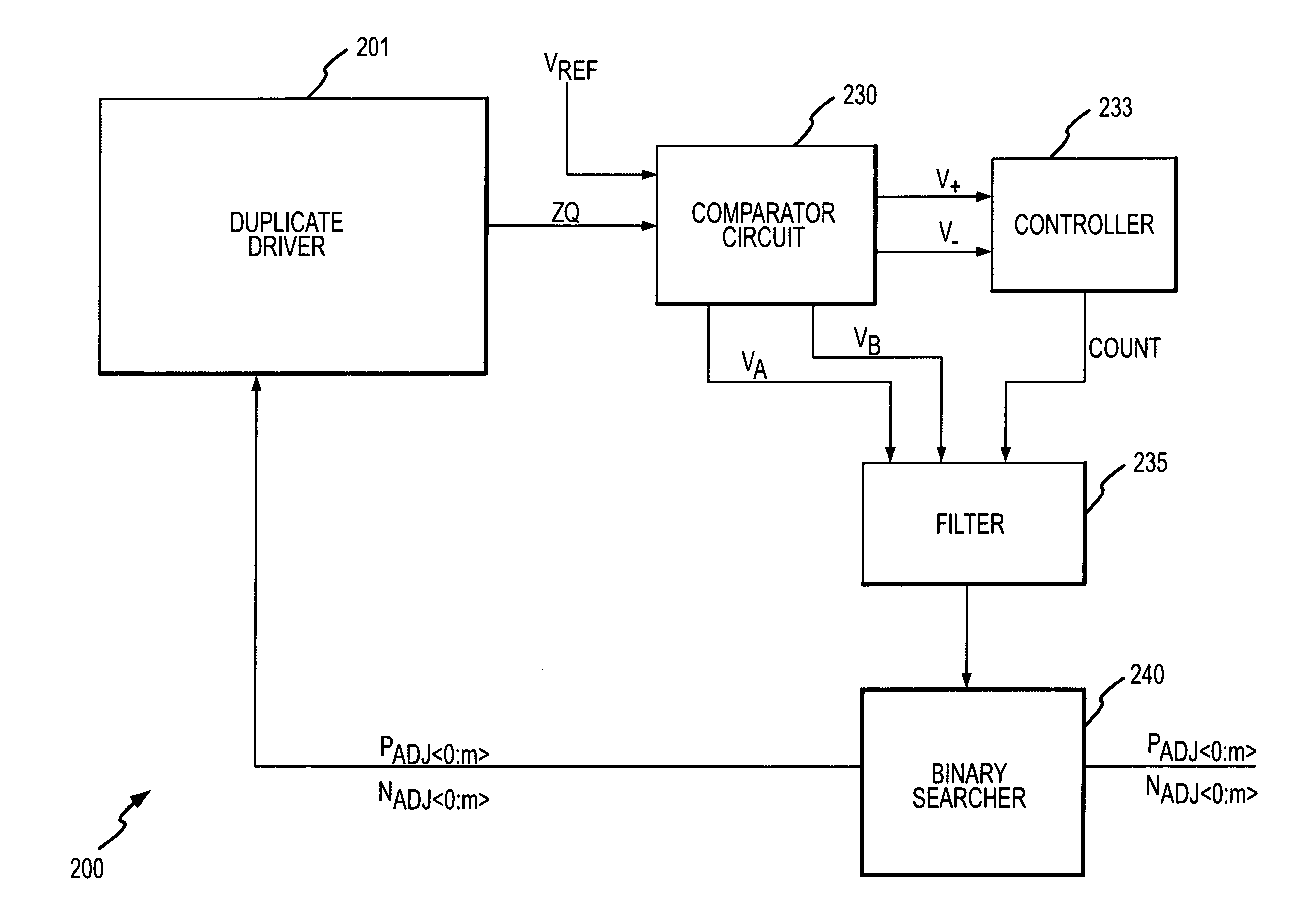
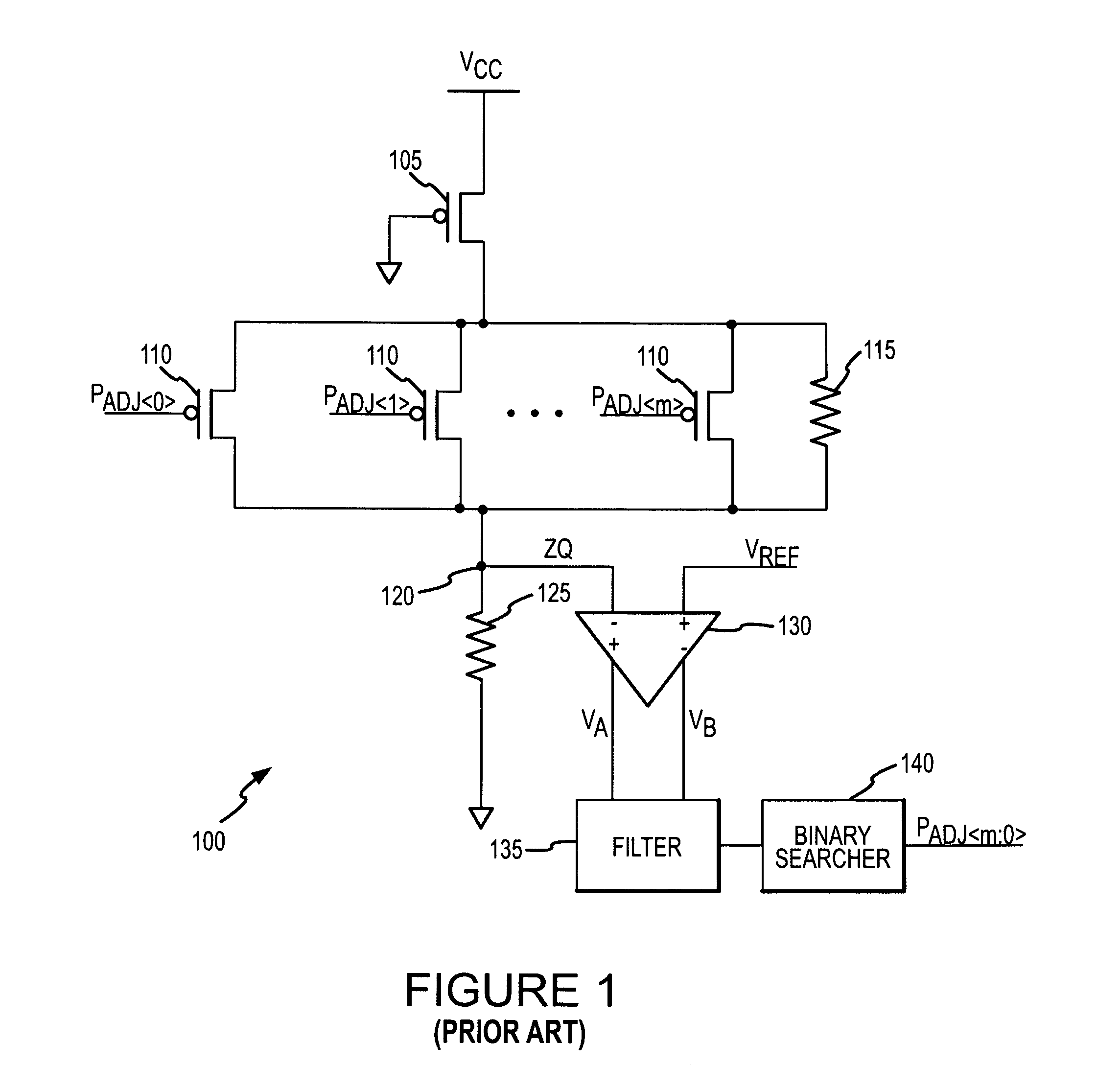
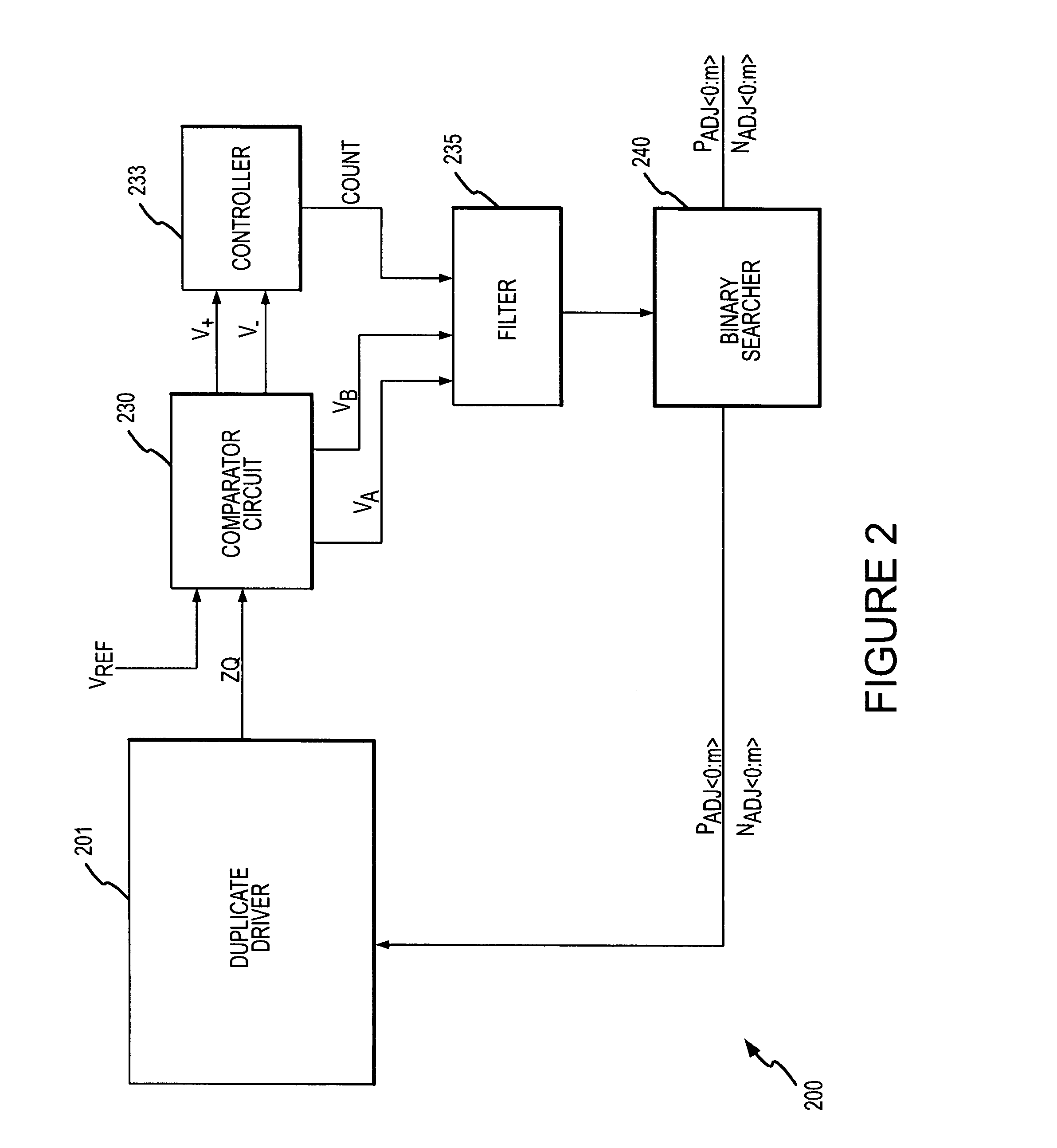
[0023]FIG. 2 shows a simplified block diagram of a calibration circuit 200 according to one embodiment of the invention, which may be adapted for an output driver to provide an impedance adjustment signal to match the driver to the impedance of external output terminals. The calibration circuit 200 includes a duplicate driver 201 like the circuit shown in FIG. 1, replicating the actual output driver to which impedance adjustment signals will be provided. T...


PUM


Abstract

A calibration circuit for matching the output impedance of a driver by calibrating adjustments to the driver is described. The calibration circuit includes a driver circuit with a plurality of calibration transistors configured to receive a plurality of adjustment signals. The calibration circuit also includes a comparator circuit, and a binary searcher. The driver provides a signal corresponding to an output impedance to the comparator circuit. The output impedance signal is compared to a target impedance, and the comparator circuit then provides logic signals to the binary searcher representing whether the output impedance is greater than the target impedance. The binary searcher then selects a type of step size and count direction, in response to the logic signals, to count the number of steps for adjusting the calibration transistors of the driver.

Description

TECHNICAL FIELD[0001]This invention relates generally to integrated circuits and, more specifically, to embodiments of circuits and methods for adjusting the impedance of an externally accessible output terminal.BACKGROUND OF THE INVENTION[0002]Integrated circuits typically include a number of input / output terminals used for communication with external circuitry. Recently developed communication networks can now transmit signals between circuitry at a rate faster than the capacity of many integrated circuits. As data is transmitted at increasingly higher speeds, new circuitry and methods are needed to accurately transmit data between integrated circuits having varying transmission rates. For example, an integrated memory device such as a dynamic random access memory (DRAM) includes both control terminals for receiving memory control signals, and data terminals for bi-directional data communication with an external system or processor. As data are transmitted at higher speeds between...

Claims


Application Information

Patent Timeline
IPC IPC(8): G11C7/02H03K19/0175H03K19/003
CPCG11C7/1051G11C7/1069G11C11/4093G11C29/02H03K19/0005G11C29/028G11C29/50008G11C2207/2254G11C29/022
Inventor MEI, SHIZHONG
Owner MICRON TECH INC
Why Eureka
Try Eureka