Methods and apparatus for operating a wind turbine

a technology of wind turbines and control apparatuses, which is applied in the direction of liquid fuel engines, vessel construction, marine propulsion, etc., can solve the problems of short-term increase in generator speed and/or electric power output that may be difficult for a controller of the wind turbine to process, and the need of new, reinforced components, etc., to achieve the effect of reducing the load acting on components and reducing the power outpu

Inactive Publication Date: 2008-05-15
GENERAL ELECTRIC CO
View PDF28 Cites 104 Cited by
  • Summary
  • Abstract
  • Description
  • Claims
  • Application Information

AI Technical Summary

Benefits of technology

[0005]In one aspect, a method for operating a wind turbine. The method includes measuring an ambient air temperature and decreasing a power output of the wind turbine if the measured ambient air temperature is below a predetermined limit to thereby facilitate reducing loads acting on components of the wind turbine.

Problems solved by technology

Operation of a wind turbine below this temperature range may require new load calculations which will exceed the design load envelope if no countermeasures are taken, possibly resulting in the need of new, reinforced components.
At least some known wind turbines, when subjected to cold weather conditions with ambient air temperature values below the lower temperature limit of the allowable temperature range, are shut off, which is disadvantageous insofar as no electric output power is generated.
Such stalling reduces a potential electric power output of the wind turbine.
Moreover, reestablishment of airflow around at least some known wind turbine rotor blades after stalling may cause a short-term increase in generator speed and / or electric power output that may be difficult for a controller of the wind turbine to process.
Such controller processing difficulty may increase a probability of the wind turbine to be disconnected from an electric grid due to over-speed and / or over-production conditions.

Method used


Image

  • Methods and apparatus for operating a wind turbine
  • Methods and apparatus for operating a wind turbine
  • Methods and apparatus for operating a wind turbine

Examples


Embodiment Construction

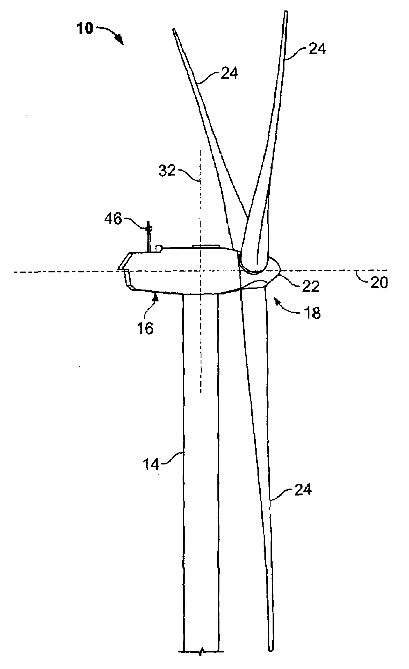
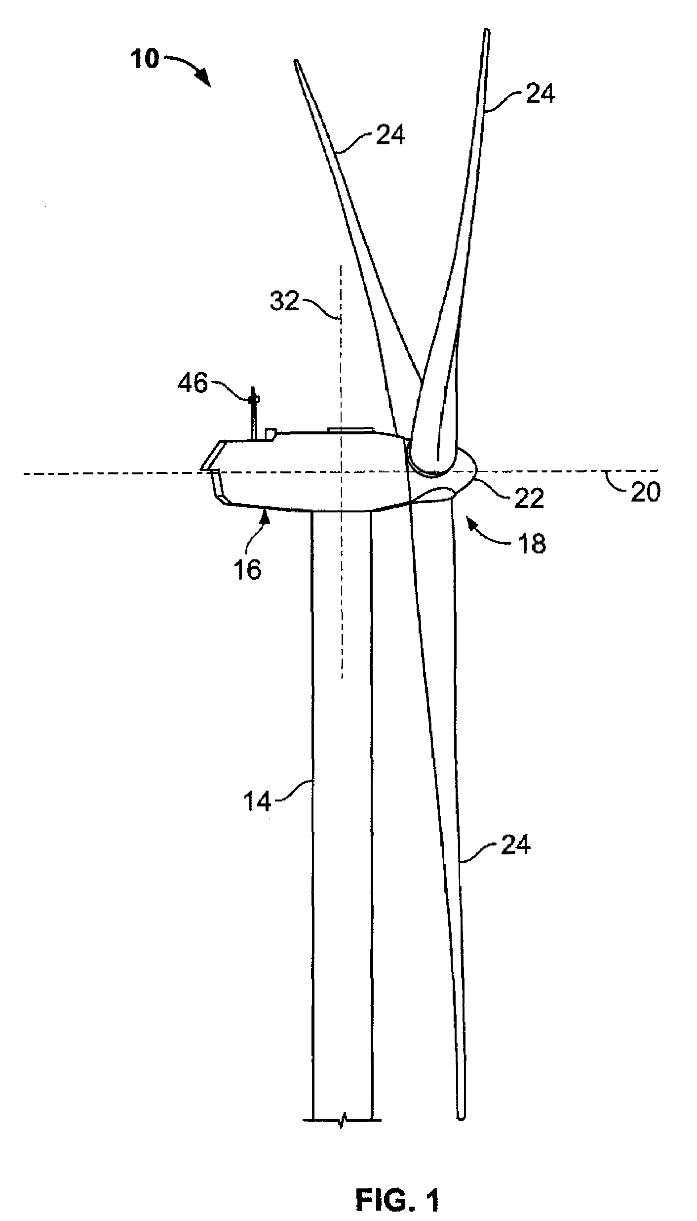
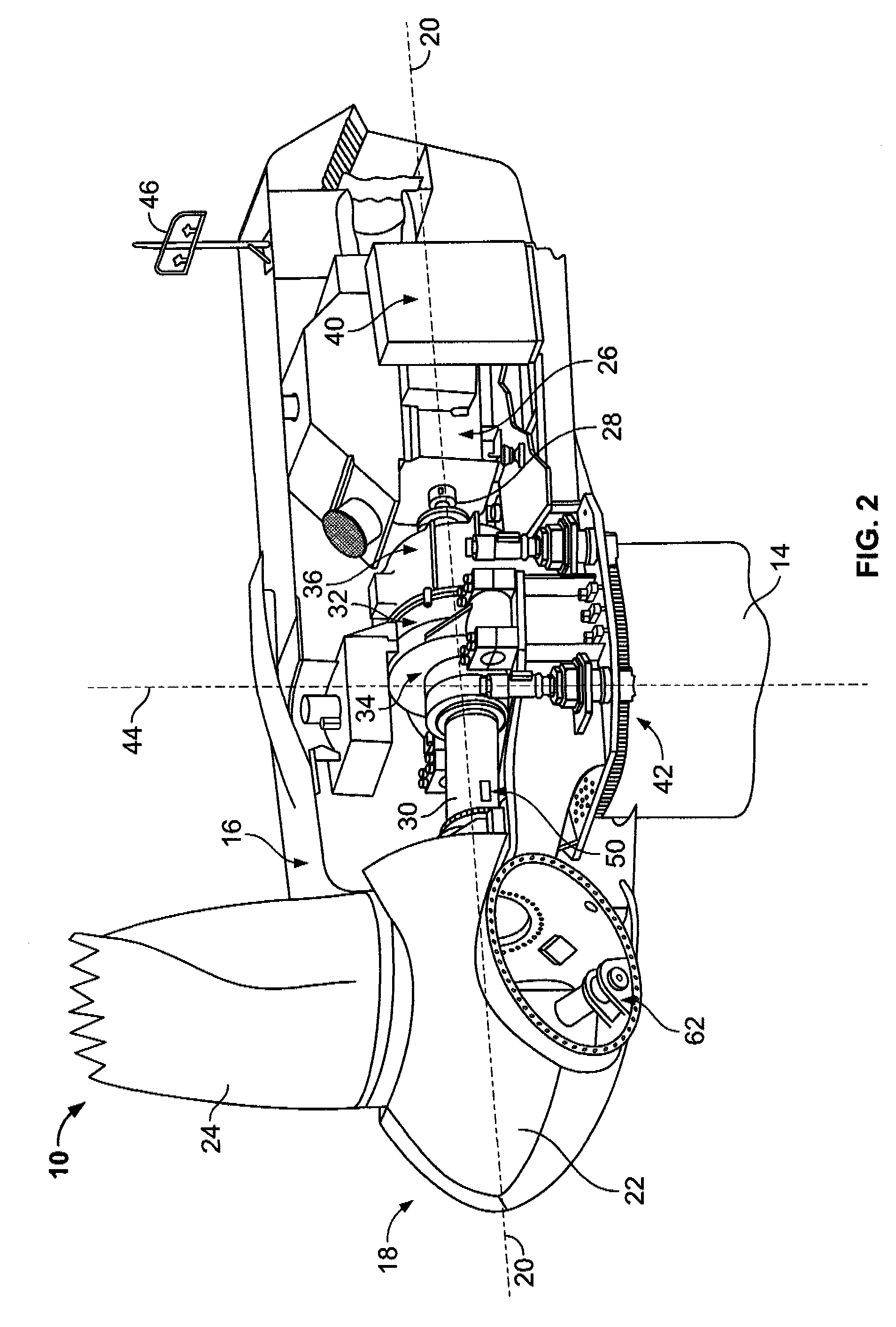
[0013]As used herein, the term “blade” is intended to be representative of any device that provides reactive force when in motion relative to a surrounding fluid. As used herein, the term “wind turbine” is intended to be representative of any device that generates rotational energy from wind energy, and more specifically, converts kinetic energy of wind into mechanical energy. As used herein, the term “wind turbine generator” is intended to be representative of any wind turbine that generates electrical power from rotational energy generated from wind energy, and more specifically, converts mechanical energy converted from kinetic energy of wind to electrical power. As used herein, the term “windmill” is intended to be representative of any wind turbine that uses rotational energy generated from wind energy, and more specifically mechanical energy converted from kinetic energy of wind, for a predetermined purpose other than generating electrical power, such as, but not limited to, p...


PUM


Abstract

A method for operating a wind turbine having at least one blade includes determining an ambient air operating envelope and controlling a power output of the wind turbine at least partially based on the determined ambient air operating envelope. Determining an ambient air operating envelope includes measuring at least one of an ambient air temperature, an ambient air pressure, an ambient air humidity, and wind turbine power output. The method also includes comparing at least one of a measured ambient air temperature, a measured ambient air humidity and a measured ambient air pressure to predetermined ambient air temperature, pressure and humidity values. The method further includes referencing the predetermined ambient air temperature, pressure and humidity values to at least one operational parameter of the wind turbine. The method also includes determining if an existing wind turbine power output is within a range associated with the determined ambient air operating envelope.

Description

BACKGROUND OF THE INVENTION[0001]This invention relates generally to wind turbines, and more specifically to methods and apparatus for controlling operation of a wind turbine.[0002]Generally, a wind turbine includes a rotor having multiple blades. The rotor is sometimes mounted within a housing, or nacelle, that is positioned on top of a base, for example a truss or tubular tower. At least some known electric utility grade wind turbines (i.e., wind turbines designed to provide electrical power to an electric utility grid) can have rotors of 30 meters (m) (98 feet (ft)) or more in diameter. The rotor blades transform mechanical wind energy into a mechanical rotational torque that drives one or more generators. The generators are sometimes, but not always, rotationally coupled to the rotor through a gearbox. The gearbox steps up the inherently low rotational speed of the turbine rotor for the generator to efficiently convert the rotational mechanical energy to electrical energy, which...

Claims


Application Information

Patent Timeline
Patent Type & Authority Applications(United States)
IPC IPC(8): B64C27/00
CPCF03D7/0224F03D7/0256F03D7/0272F03D7/0292F03D7/043F03D11/0091F05B2270/323F05B2270/324F05B2270/325F05B2270/504Y02E10/723F05B2270/303F03D17/00Y02E10/72
Inventor UPHUES, ULRICHCHRISTENSON, CRAIG LEONARDROGERS, DONALDGREGG, PETERKOOIJMAN, HENK-JANLECLAIR, RYANSIEBERS, THOMASORMEL, FRANK T.
Owner GENERAL ELECTRIC CO
Why Eureka
Try Eureka