Heart assist device with expandable impeller pump

a technology of expandable impellers and heart assist devices, which is applied in the direction of liquid fuel engines, vessel construction, marine propulsion, etc., can solve the problems of increasing the stress of heart failure cases, impractical or impossible to insert the size of the pump needed for sustaining adequate blood flow, and claiming many lives per year, and achieves the effect of increasing blood flow through the blood pump

Active Publication Date: 2008-05-15
PENN STATE RES FOUND +2
View PDF99 Cites 254 Cited by
  • Summary
  • Abstract
  • Description
  • Claims
  • Application Information

AI Technical Summary

Benefits of technology

[0006] The present invention may be used as an LVAD, a right ventricular assist device (“RVAD”) or in other situations that may benefit from a blood pump that is expandable in situ after being inserted into the body of a patient. The blood pump has an impeller design that allows compression and expansion of the impeller at the discretion of the operator. This compression / expansion feature allows for increased blood flow through the blood pump due to an increase, by expansion, of the impeller size, thereby producing a blood flow capable of sustaining human life without the need for significant contribution by the heart muscle. The blood flow provided is typically at least 4 liters per minute of blood, the flow that is usually sufficient to sustain life.

Problems solved by technology

Heart disease is a major problem in society, and claims many lives per year.
Surgical placement is required, since it is presently impractical or impossible to insert a pump of the size needed for sustaining adequate blood flow percutaneously.
Surgical insertion, however, can cause additional serious stresses in heart failure cases.
However, the conventional fixed cross-sectional diameter of such an LVAD cannot fit through the femoral artery of the leg in which it must travel to be positioned into the left ventricle.
While the pumping rate can be increased by increasing the diameter of the device, particularly the diameter of the impeller, the size of the femoral artery is a limiting factor for percutaneous insertion.

Method used


Image

  • Heart assist device with expandable impeller pump
  • Heart assist device with expandable impeller pump
  • Heart assist device with expandable impeller pump

Examples


Embodiment Construction

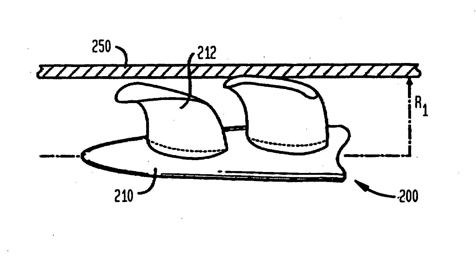
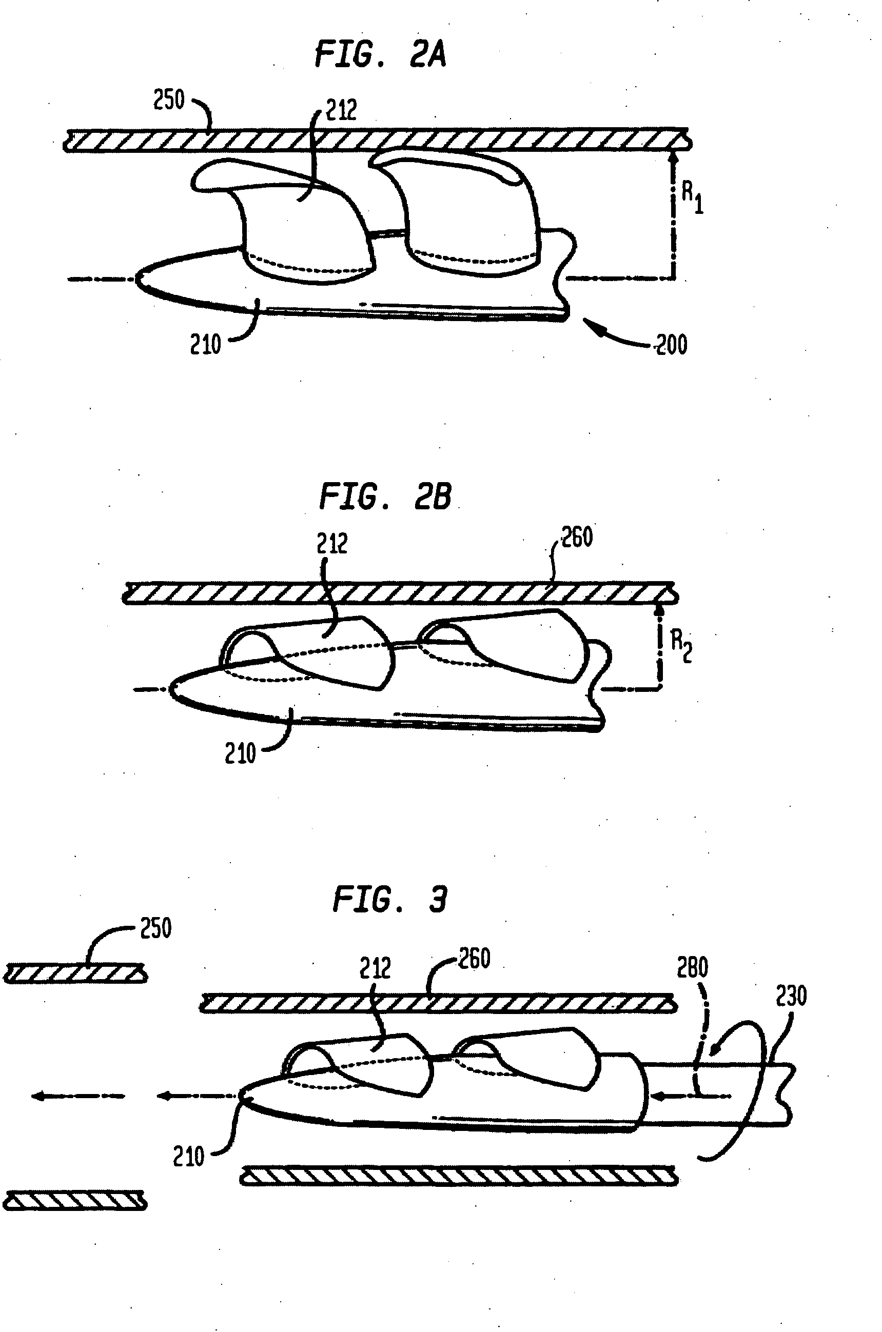
[0044] An impeller according to embodiments of the present invention includes a hub, and at least one blade supported by the hub. The impeller may have a deployed configuration in which the blade extends away from the hub, and a stored configuration in which the impeller is radially compressed, for example by folding the blade towards the hub.

[0045] In some embodiments, the outer edge of a blade may have a winglet. The impeller also may have a trench or indentation proximate to a blade root to facilitate folding of the blade and / or to reduce shear stresses in the fluid flow induced by rotation of the impeller.

[0046] Some embodiments of the present invention include impellers that do not radially compress, but retain a generally constant configuration. Impellers according to the present invention may be used in various applications, including improved blood pumps.
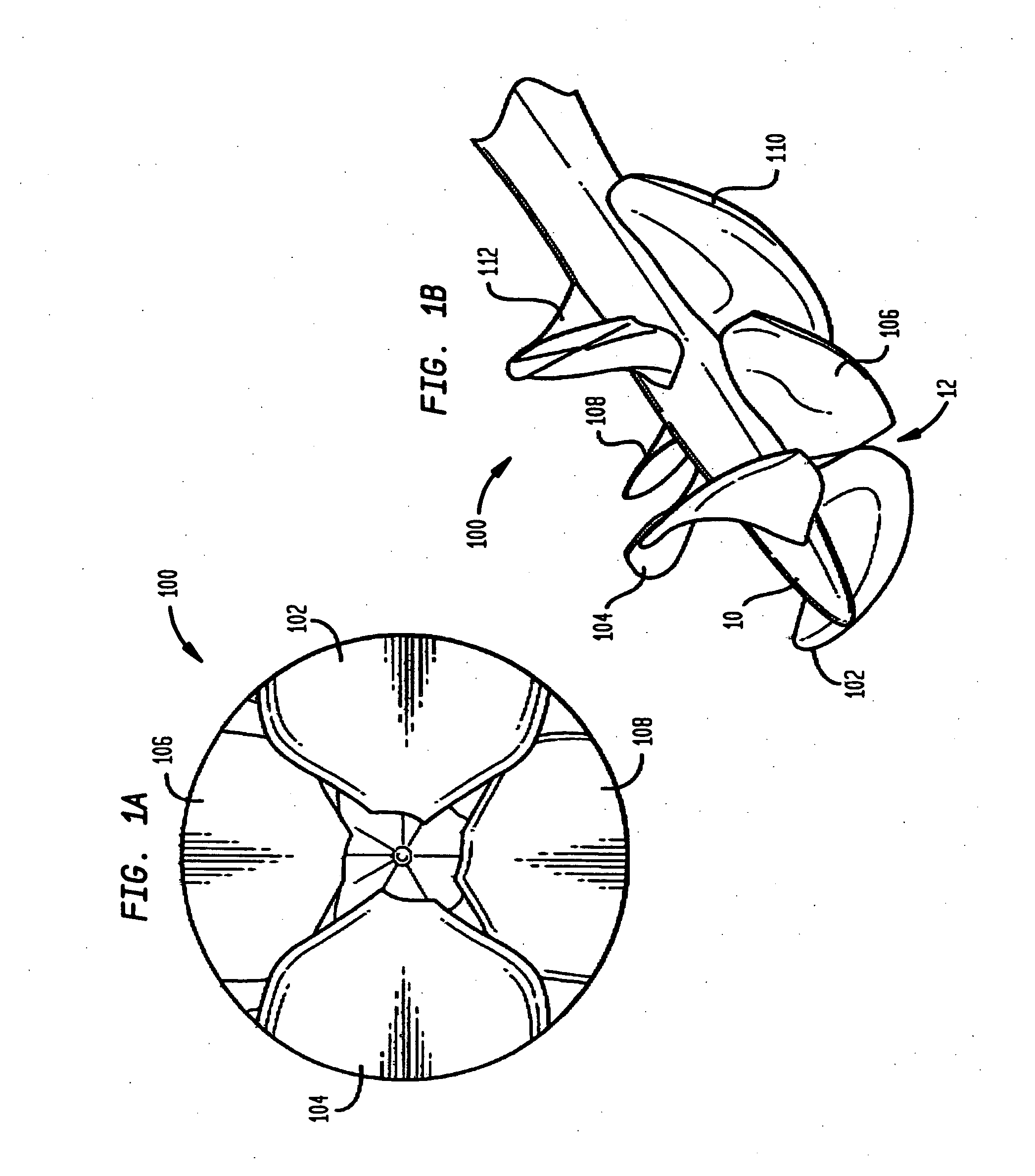
Blade Rows

[0047] Impellers according to embodiments of the present invention may include a plurality of blades which ...


PUM


Abstract

An impeller includes a hub and at least one blade supported by the hub. The impeller has a stored configuration in which the blade is compressed so that its distal end moves towards the hub, and a deployed configuration in which the blade extends away from the hub. The impeller may be part of a pump for pumping fluids, such as pumping blood within a patient. A blood pump may include a cannula having a proximal portion with a fixed diameter, and a distal portion with an expandable diameter. The impeller may reside in the expandable portion of the cannula. The cannula may have a compressed diameter which allows it to be inserted percutaneously into a patient. Once at a desired location, the expandable portion of the cannula may be expanded and the impeller expanded to the deployed configuration. A flexible drive shaft may extend through the cannula for rotationally driving the impeller within the patient's body.

Description

CROSS-REFERENCE TO RELATED APPLICATIONS [0001] This application claims the benefit of the filing dates of U.S. Provisional Application Nos. 60 / 785,299, filed on Mar. 23, 2006 and 60 / 785,531, filed on Mar. 23, 2006, the disclosures of which are hereby incorporated by reference herein. Further, the entire disclosures of U.S. Provisional Application No. 60 / 610,938, filed on Sep. 17, 2004, and U.S. patent application Ser. No. 11 / 227,277, filed on Sep. 15, 2005, are hereby incorporated by reference herein.FIELD OF THE INVENTION [0002] The present invention relates to fluid pumping impellers, more particularly to expandable fluid pumping impellers. Still more particularly, the present invention relates to blood pumps such as left or right ventricular assist devices with an expandable impeller for treatment of heart disease. BACKGROUND OF THE INVENTION [0003] Heart disease is a major problem in society, and claims many lives per year. After a heart attack, only a small number of patients c...

Claims


Application Information

Patent Timeline
Patent Type & Authority Applications(United States)
IPC IPC(8): B64C11/28A61K9/22A61M60/13A61M60/174A61M60/237A61M60/414A61M60/808A61M60/824A61M60/857
CPCA61M1/101A61M2205/0266F04D3/00A61M1/122F04D29/247A61M1/1024A61M1/1034F04D29/181B33Y80/00F05B2240/311F05B2280/5001A61M60/824A61M60/829A61M60/414A61M60/808A61M60/174A61M60/237A61M60/13A61M60/865A61M60/806A61M60/148F04D29/528F04D3/02F04D29/542
Inventor MCBRIDE, MARK W.BOGER, DAVID A.CAMPBELL, ROBERT L.DILLON, GREGORY P.HAMBRIC, STEPHEN A.KUNZ, ROBERT F.LESCHINSKY, BORISMALLISON, THOMAS M.RUNT, JAMES P.WALSH, JUSTIN M.
Owner PENN STATE RES FOUND
Why Eureka
Try Eureka