Running Control Apparatus For Vehicle

a running control and vehicle technology, applied in the direction of external condition input parameters, non-deflectable wheel steering, brake components, etc., can solve the problem of slow response of the vehicle to the driver's driving operation, difficulty in dealing with understeer of the vehicle, and vehicle speed needs to be changed

Inactive Publication Date: 2008-05-15
TOYOTA JIDOSHA KK
View PDF11 Cites 16 Cited by
  • Summary
  • Abstract
  • Description
  • Claims
  • Application Information

AI Technical Summary

Benefits of technology

[0008]The invention is made in view of the aforementioned problem in the conventional running control apparatus that includes steering means for steering a steering wheel independently of steering operation performed by a driver, and braking / driving force control means for controlling braking / driving force for each wheel. An object of the invention is to appropriately allocate a target turning control amount to steering means and braking / driving force control means according to the driving mode desired by an occupant and the intention of a driver by taking into account the driving mode desired by the occupant and the intention of the driver when the target turning control amount is divided to a target turning control amount allocated to the control of the steering angle of a steering wheel and a target turning control amount allocated to the control of braking / driving force, whereby the running movement of the vehicle is controlled appropriately and effectively.

Problems solved by technology

However, the vehicle moves in slower response to driver's driving operation than when the running movement is controlled by controlling the braking / driving force.
Also, it is difficult to deal with understeer of the vehicle.
However, the vehicle speed needs to be changed, that is, the vehicle needs to be accelerated or decelerated.
Therefore, the target turning control amount cannot be appropriately allocated to the steering means and to the braking / driving force control means according to the running mode desired by the occupant and the intention of the driver.

Method used


Image

  • Running Control Apparatus For Vehicle
  • Running Control Apparatus For Vehicle
  • Running Control Apparatus For Vehicle

Examples


first embodiment

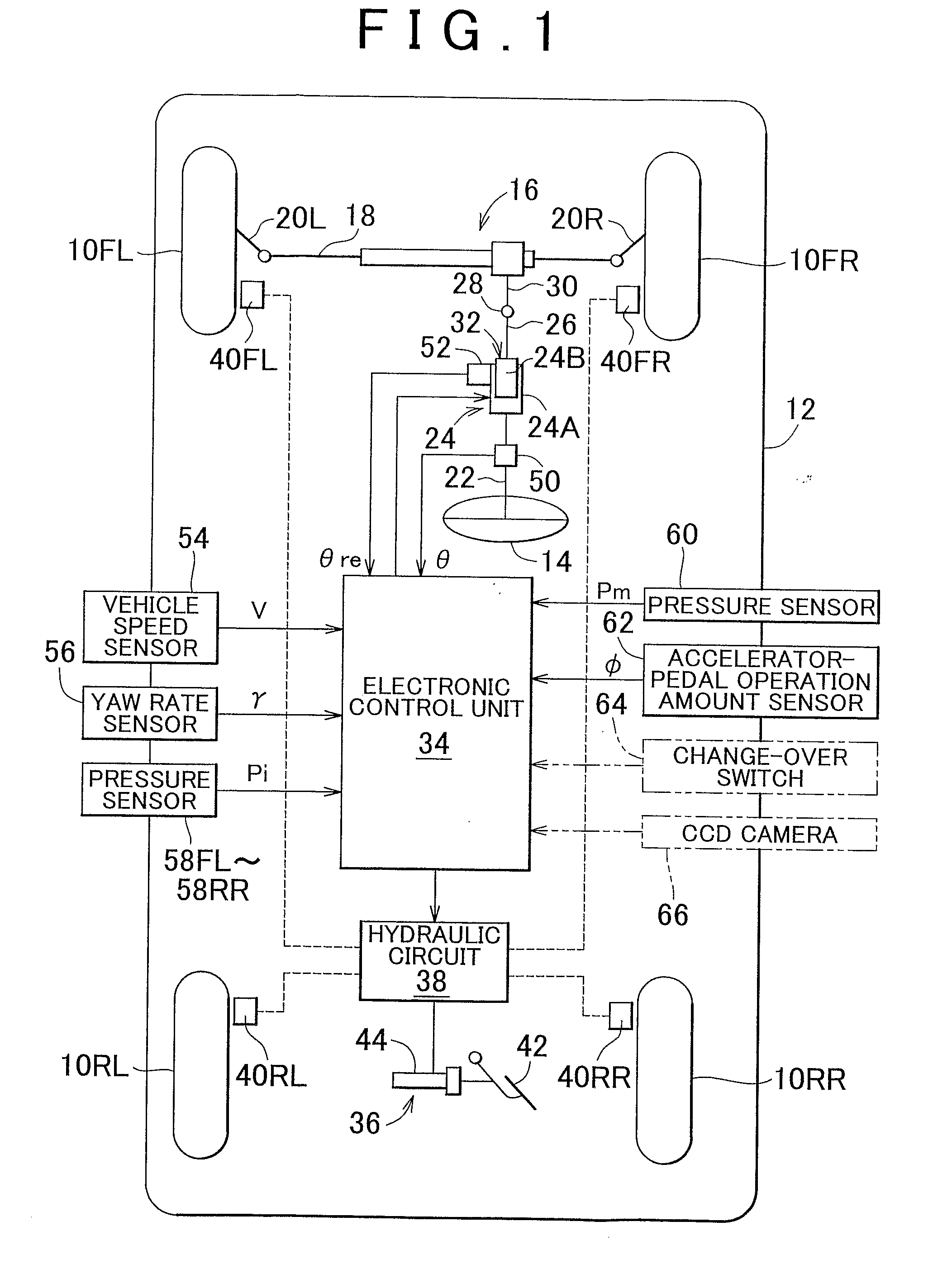
[0056]FIG. 1 is a schematic diagram showing the configuration of a running control apparatus for a vehicle according to a first embodiment of the invention, which is applied to a vehicle that includes a steering-angle changing device that functions as an automatic steering device.

[0057]In FIG. 1, a vehicle 12 includes a front-left wheel 10FL, a front-right wheel 10FR, a rear-left wheel 10RL, and a rear-right wheel 10RR. The front-left and front-right wheels 10FL and 10FR are steering wheels, which are steered by a rack and pinion type power steering device 16 via a rack-bar 18 and tie-rods 20L and 20R. The power steering device 16 is driven in response to the movement of a driver's steering wheel 14 operated by a driver.

[0058]The driver's steering wheel 14 is connected to a pinion shaft 30 of the power steering device 16 via an upper steering shaft 22, a steering-angle changing device 24, a lower steering shaft 26, and a universal joint 28. The upper steering shaft 22 is considered ...

second embodiment

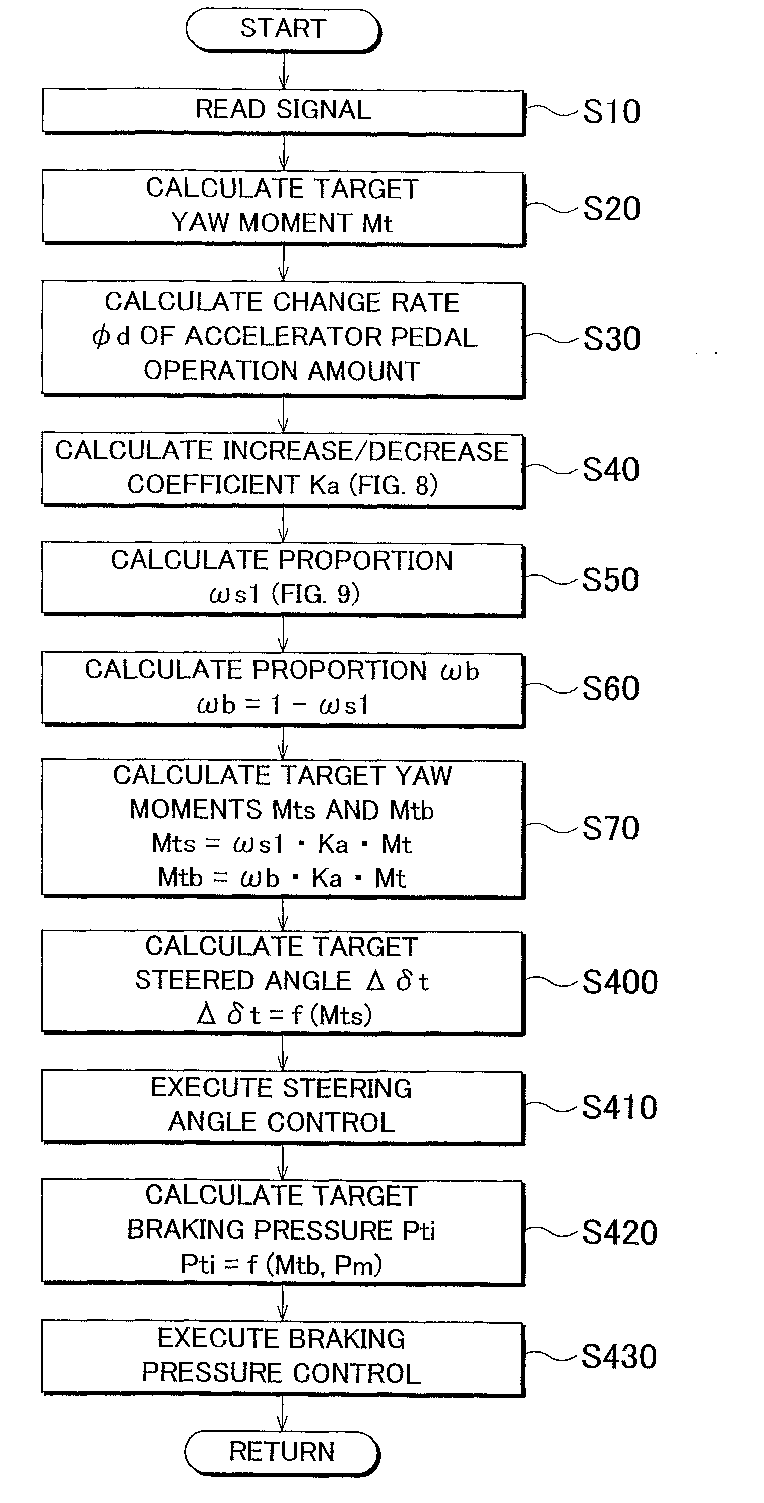
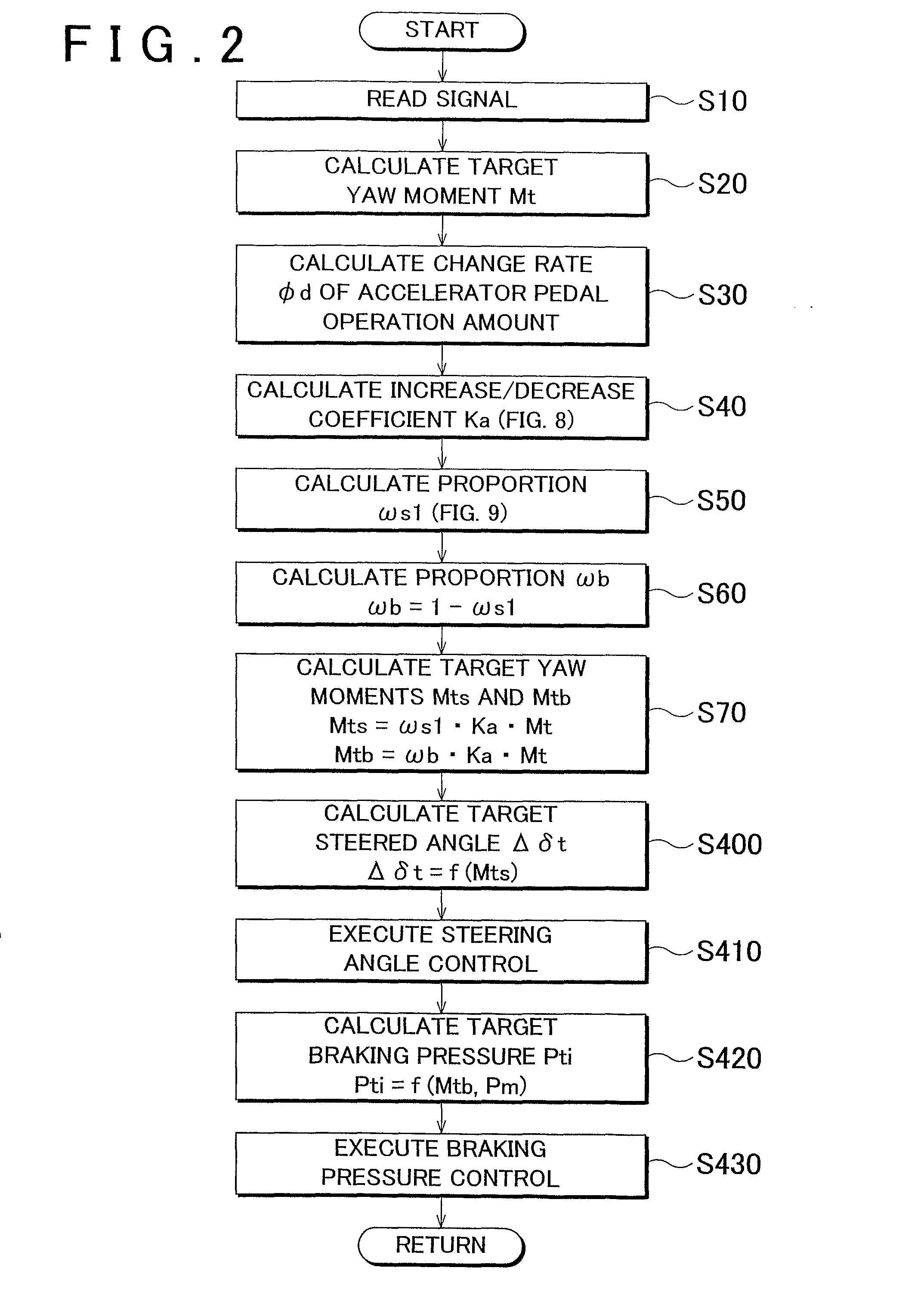
[0082]FIG. 3 is a flowchart showing a running control routine executed by a running control apparatus for a vehicle according to a second embodiment of the invention. In FIG. 3, the same steps as those in FIG. 2 are denoted by the same step numbers. Similarly, the same steps as those in FIG. 2 are denoted by the same step numbers also in FIG. 4 to FIG. 7.

[0083]In the second embodiment, the electronic control unit 34 does not receive the signal indicating the accelerator pedal operation amount φ from the accelerator-pedal operation amount sensor 62. However, as shown by a two-dot chain line in FIG. 1, the electronic control unit 34 receives a signal indicating the driving mode. The driving mode of the vehicle is set to a sport mode or a standard mode by a change-over switch 64 operated by the driver. When the driving mode of the vehicle is set to the sport mode, the vehicle moves in quick response to the driver's driving operation, as compared to when the driving mode is set to the s...

third embodiment

[0092]FIG. 4 is a flowchart showing a running control routine executed by a running control apparatus for a vehicle according to a third embodiment of the invention.

[0093]In the third embodiment, when the driver operates a driver identification button (not shown in FIG. 1), the driver is identified. Drivers, values of an increase / decrease coefficient Kc, and values of a proportion ωs3 used to allocate the target yaw moment to the steering angle control are registered in the electronic control unit 34, for example, as shown in Table 1. The value of the increase / decrease coefficient Kc and the value of the proportion ωs3 indicate the driving mode desired by the driver. The registered drivers correspond to the respective driver identification buttons.

TABLE 1Increase / decreasecoefficient KcProportion ωs3Driver A1.00.2Driver B0.80.5Driver C0.21.0

[0094]After the driver is identified by operation of the driver identification button, the electronic control unit 34 sets the increase / decrease ...


PUM


Abstract

A target yaw moment Mt of a vehicle is calculated to make the vehicle run stably (S20). The change rate φd of an accelerator pedal operation amount φ is calculated (S30). Based on the change rate φd, a proportion ωs1 for a steering angle control is calculated (S50). When the change rate φd is a positive value, the proportion ωs1 gradually increases as the change rate φd increases. A proportion ωb for a braking force control is calculated by subtracting the proportion ωs1 from 1 (1−ωs1) (S60). Based on the proportions ωs1 and ωb, a target yaw moment Mts for the steering angle control and a target yaw moment Mtb for the braking force control are calculated (S70). A steering-angle changing device (24) and a braking device (36) are controlled based on the target yaw moments Mts and Mtb, respectively (S400 to S430).

Description

BACKGROUND OF THE INVENTION[0001]1. Field of the Invention[0002]The invention relates to a running control apparatus for a vehicle. More specifically, the invention relates to a running control apparatus that controls the running movement of a vehicle by controlling the steering angle of a steering wheel and the braking / driving force for the wheel.[0003]2. Description of the Related Art[0004]Japanese Patent Application Publication No. JP-A-2003-175749 describes an example of a running control apparatus for a vehicle such as an automobile. The running control apparatus includes steering means, braking / driving force control means, calculation means, division means, and control means. The steering means steers a steering wheel, independently of steering operation performed by a driver. The braking / driving force control means controls the braking / driving force for each wheel. The calculation means calculates a target turning control amount, such as a target yaw moment of the vehicle. Th...

Claims


Application Information

Patent Timeline
Patent Type & Authority Applications(United States)
IPC IPC(8): B60T8/1755B60W10/18B60W10/20B60W10/00B60W10/188B60W30/00B60W30/02B60W30/045B62D5/04B62D6/00B62D101/00B62D113/00B62D137/00
CPCB60T8/1755B60T2210/24B60T2260/02B60W10/18B60W10/20B60W30/02B62D6/007B60W40/09B60W2540/106B60W2550/143B60W2710/18B60W2710/20B62D6/003B60W30/182B60W2552/20B60W2552/30B60W40/114
Inventor SAKUGAWA, JUNMONZAKI, SHIRO
Owner TOYOTA JIDOSHA KK
Why Eureka
Try Eureka