Exhaust gas treatment method and system for cement burning facility

a technology of exhaust gas treatment and cement burning facility, which is applied in the direction of auxillary pretreatment, separation process, filtration separation, etc., can solve the problems of blockage and blockage of the facility, and achieve the effect of preventing an increase in chlorine bypass amount, reducing the rate of chlorine particles, and reducing the amount of chlorine bypass

Active Publication Date: 2010-04-08
MITSUBISHI UBE CEMENT CORP
View PDF6 Cites 9 Cited by
  • Summary
  • Abstract
  • Description
  • Claims
  • Application Information

AI Technical Summary

Benefits of technology

[0040]Additionally, the classification particle size in the solid-gas separation means is set to between 15 μm and 30 μm. As described above, this is because a classification particle size of less than 15 μm extremely increases the rate of chlorine particles in the fine powder dust, thus hindering the chlorine concentration of the fine powder dust from being reduced to at most 20%, while precluding the amount of the fine powder dust from being maintained between 50 g / m3N and 150 g / m3M. On the other hand, a classification particle size of more than 30 μm increases the amount of fine powder dust to be finally treated, above 150 g / m3N, while preventing an increase in chlorine bypass amount. This reduces economic efficiency.
[0041]Moreover, as described above, the cement material fed from the lowermost part of the preheater into the kiln inlet part via the material chute is preferably used as the cement material dispersed in the exhaust gas to increase the dust concentration of the extracted gas. This obviates the need to substantially change the existing facility. Furthermore, this cement material has a high temperature and thus preferably contains much activated CaO. Additionally, adjustment of the temperature requires dispersion of a relatively large amount of the cement material. Thus, advantageously, the chlorine concentration of the fine powder dust can be easily set to at most 20% by increasing the dust concentration of the extracted gas.
[0042]Furthermore, in parallel with the dispersion of the cement material fed into the kiln inlet part from the material chute, a cement material at 600° C. to 700° C. in the preheater, and a raw cement material exhibiting a low temperature of 50° C. to 100° C. before conveyance to the preheater may be supplied in order to adjust the temperature in the kiln inlet part. In this case, since the temperatures of these cement materials are much lower than that of the cement material fed from the material chute, dispersing a small amount of either of the cement materials in the exhaust gas enables an efficient reduction in the temperature of the extracted gas.
[0043]As a result, the present invention enables prevention of possible draft blockage in the extracted gas duct caused by an increase in dust concentration. Furthermore, a reduction in the temperature of the exhaust gas advantageously allows the above-described possible coating to be prevented.

Problems solved by technology

In this case, for example, the possible deliquescence of the chlorine component may result in the likelihood of coating that may cause blockage and clogging in the facility.

Method used


Image

  • Exhaust gas treatment method and system for cement burning facility
  • Exhaust gas treatment method and system for cement burning facility
  • Exhaust gas treatment method and system for cement burning facility

Examples


Embodiment Construction

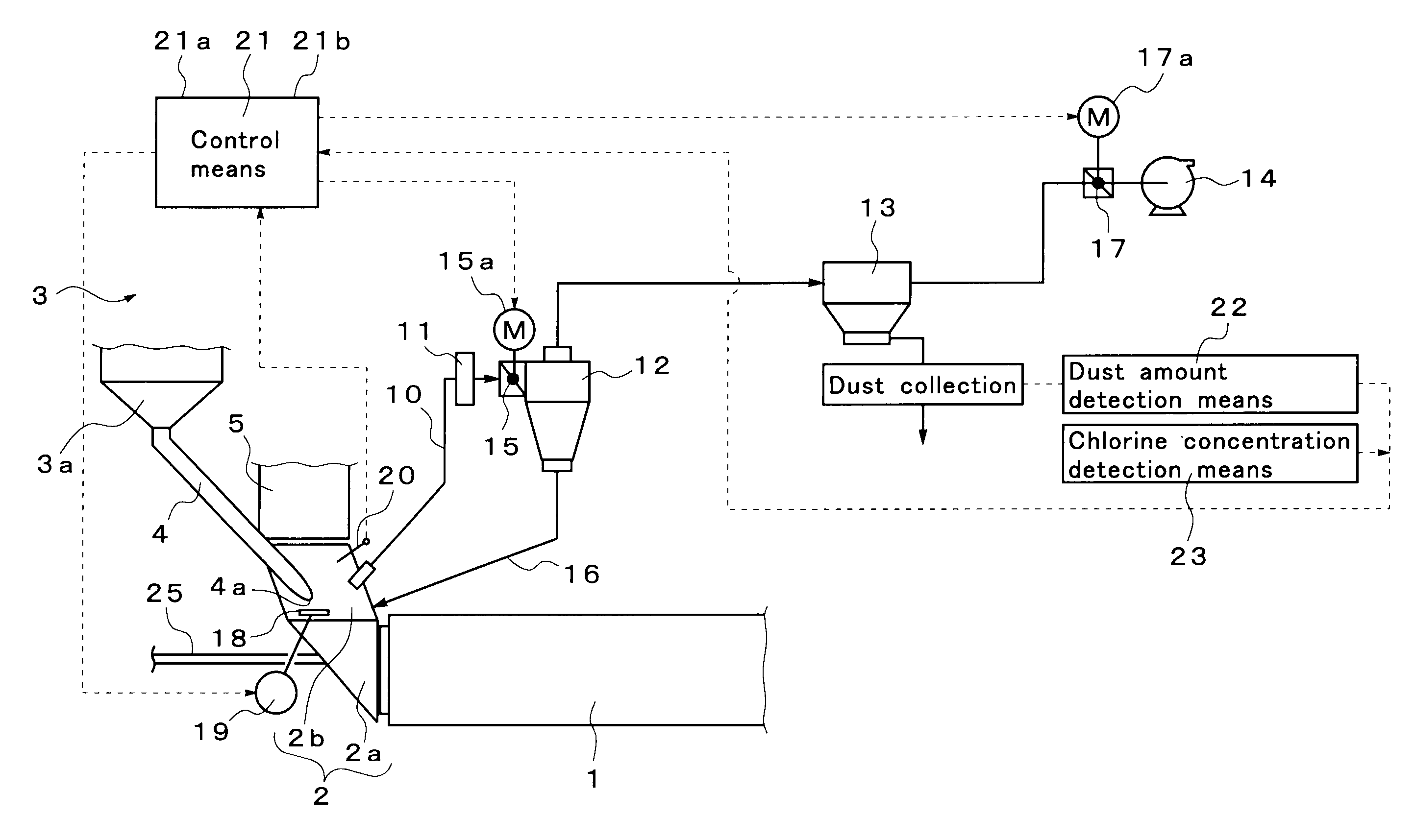
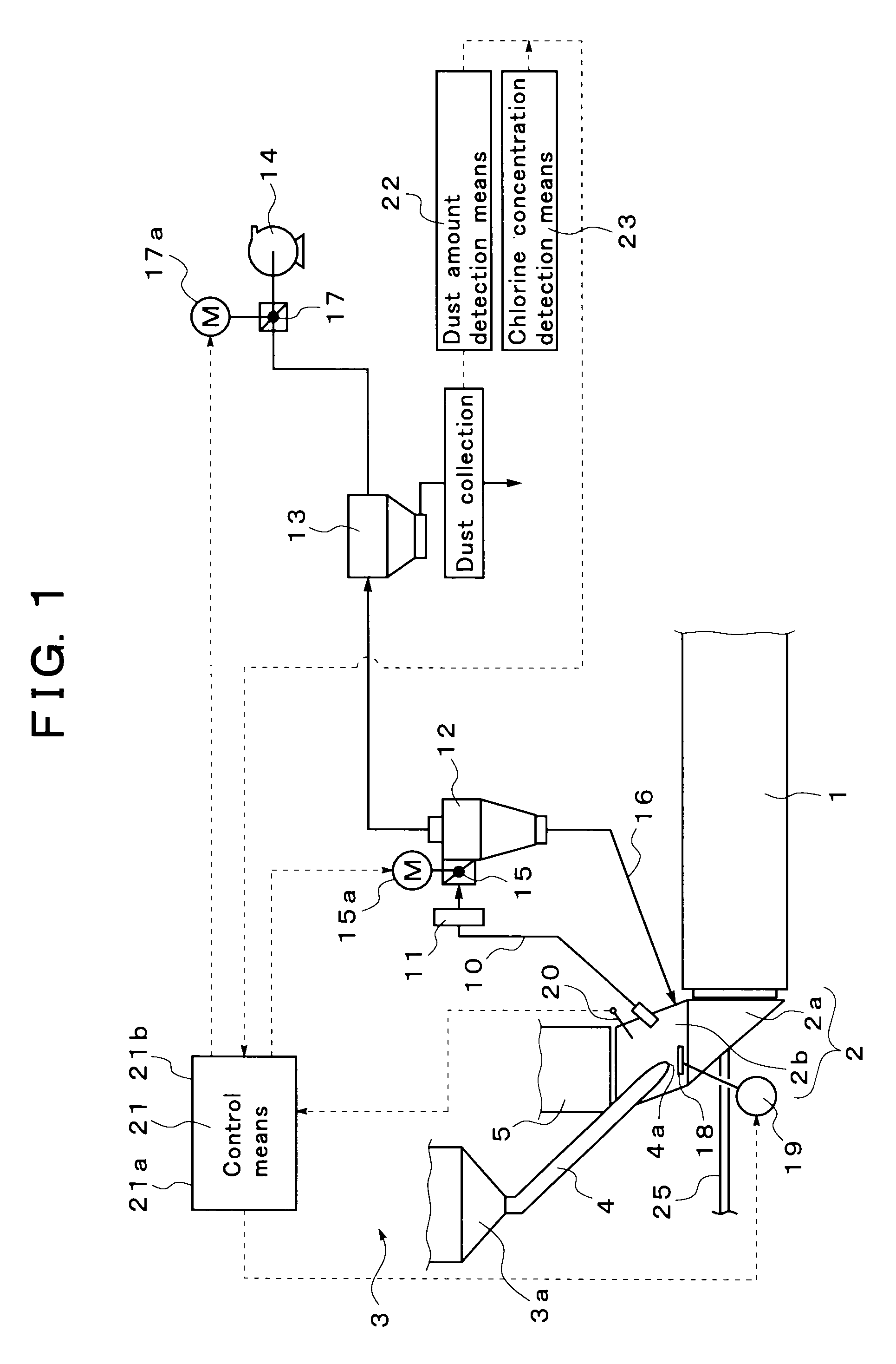
[0069]FIG. 1 shows an embodiment of an exhaust gas treatment system for a cement burning facility according to the present invention.

[0070]First, a cement manufacturing facility in which the exhaust gas treatment system is installed will be described. Reference numeral 1 in FIG. 1 denotes a cement kiln configured to burn a cement material. The cement kiln 1 is a rotary kiln configured so as to be axially rotatable. In the left end part of the figure, a kiln inlet part 2 is provided which includes a kiln inlet part housing 2a supporting the rotary portion, and a rising part 2b of the kiln inlet part housing.

[0071]Furthermore, a preheater 3 configured to preheat a cement material is provided on the upper stage side of the kiln inlet part 2. A main burner configured to heat the inside of the kiln is provided in a kiln outlet part (not shown in the drawings) located in the right of the figure.

[0072]Here, the preheater 3 is composed of a plurality of stages (for example, four stages) of ...


PUM

PropertyMeasurementUnit
particle sizeaaaaaaaaaa
temperatureaaaaaaaaaa

Abstract

An object of this invention is to provide an exhaust gas treatment method and system for a cement burning facility which allows the handling property of collected powder dust to be improved and which enables smooth removal of hydrogen chloride that may result from burning of organic sludge. When part of exhaust gas in a lowermost part of a preheater 3 or a kiln inlet part 2 of a cement kiln 1 is extracted to obtain extracted gas, a cement material is dispersed, and the disperse amount of the cement material is adjusted so as to maintain the temperature of the extracted gas between 950° C. and 1,150° C. The extracted gas is cooled to at most the melting point of a chlorine compound. Then, solid-gas separation device 12 adjusts a classification particle size to between 15 μm and 30 μm. Dust trap 13 collects and removes fine powder dust with a particle size equal to or smaller than the classification particle size. Thus, the amount of fine powder dust collected by the dust trap is maintained between 50 g/m3N and 150 g/m3N, with the concentration of chlorine in the collected fine powder dust set to between 5% and 20%.

Description

BACKGROUND OF THE INVENTION[0001]1. Field of the Invention[0002]The present invention relates to an exhaust gas treatment method and system for a cement burning facility using a chlorine bypass to inhibit a possible increase in the concentration of chlorine in the system of the cement burning facility.[0003]2. Description of the Related Art[0004]In recent years, in order to solve waste disposal problems, various wastes are used as part of a cement material or part of a heating fuel used in a cement kiln. However, when wastes such as a synthetic resin are fed into the cement kiln as part of the fuel, a volatile chlorine component is generated during combustion. The chlorine component is entrained in exhaust gas discharged from the cement kiln and fed to an upper stage side of a preheater. However, when the atmosphere temperature decreases to at most the melting point of the chlorine component as the exhaust gas is transferred to the upper stage side of the preheater, the chlorine com...

Claims


Application Information

Patent Timeline
Patent Type & Authority Applications(United States)
IPC IPC(8): C04B7/26B01D50/00B01D45/12
CPCB01D45/12B01D46/02C04B7/4423C04B7/24C04B7/364B01D50/002Y02W10/40Y02P40/125Y02P40/10B01D50/20B01D46/00B01D53/00C04B7/60
Inventor KOMATSU, YOSHIAKIISHIZAKI, MICHIOSHIMA, HIROKAZUMATSUDA, HIROYUKI
Owner MITSUBISHI UBE CEMENT CORP
Why Eureka
Try Eureka