Responder route and site-specific critical data system

Inactive Publication Date: 2008-05-15
NEEDHAM FRANK A +3
View PDF2 Cites 35 Cited by
  • Summary
  • Abstract
  • Description
  • Claims
  • Application Information

AI Technical Summary

Benefits of technology

[0013]The system provides emergency responders with critical information as they are in the process of reaching the incident site, thereby allowing for time to assess conditions and make advance decisions regarding: 1) equipment deployment; 2) equipment position; 3) crew assignments; 4) the impact of site characteristics on containment plans; 5) nearby water resources; 6) poten

Problems solved by technology

Rural Fire and Emergency Medical Service (“EMS”) Districts face unique challenges based on their large area and the lack of funds and specialized equipment compared to urban fire districts.
Rural fire districts also suffer from lack of sufficient information for “pre-fire” plans, a term used to describe information about a road, structure or home site, which the districts maintain in advance of an emergency event.
The districts incur the costs of moving personnel and equipment to the various sites and back to the district station.
However, in the course of the training runs, the fire and EMS Districts typically do not attempt to record the terrain, road surfaces, vegetative fuels, or other risk enhancers.
Nor is information recorded or readily available for how to deploy equipment once the responder reaches a particular site.
Districts traditionally have not been able to afford to adequately collect or maintain this information due to time constraints and limited crew availability.
As a result, the commanders are often left making critical decisions based on: 1) pre-fire plans that are maintained on index cards that contain limited information; 2) pre-fire plans maintained on hand-written sheets in binders that make sharing information with more than one person difficult; 3) pre-fire plans that contain little to no information regarding the physical c

Method used


Image

  • Responder route and site-specific critical data system
  • Responder route and site-specific critical data system
  • Responder route and site-specific critical data system

Examples


Embodiment Construction

[0023]The following detailed description illustrates the invention by way of example, not by way of limitation of the scope, equivalents or principles of the invention. The invention is illustrated in the several figures, and is of sufficient complexity that the many parts, interrelationships, and sub-combinations thereof cannot be fully illustrated in a single patent-type drawing. For clarity and conciseness, several of the drawings show in schematic, or omit, parts that are not essential in that drawing to a description of a particular feature, aspect or principle of the invention being disclosed. Thus, the best mode embodiment of one feature may be shown in one drawing, and the best mode of another feature will be called out in another drawing.

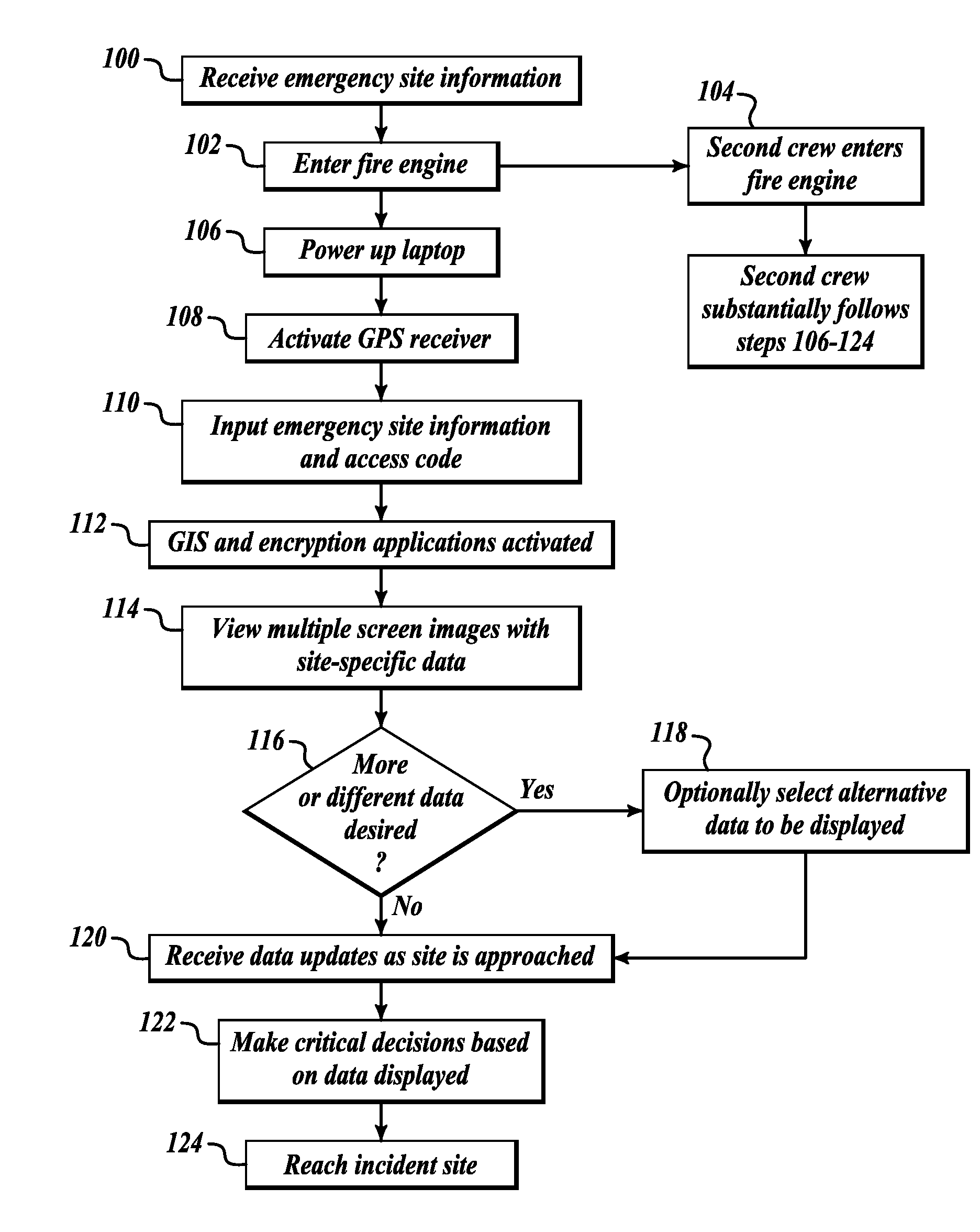
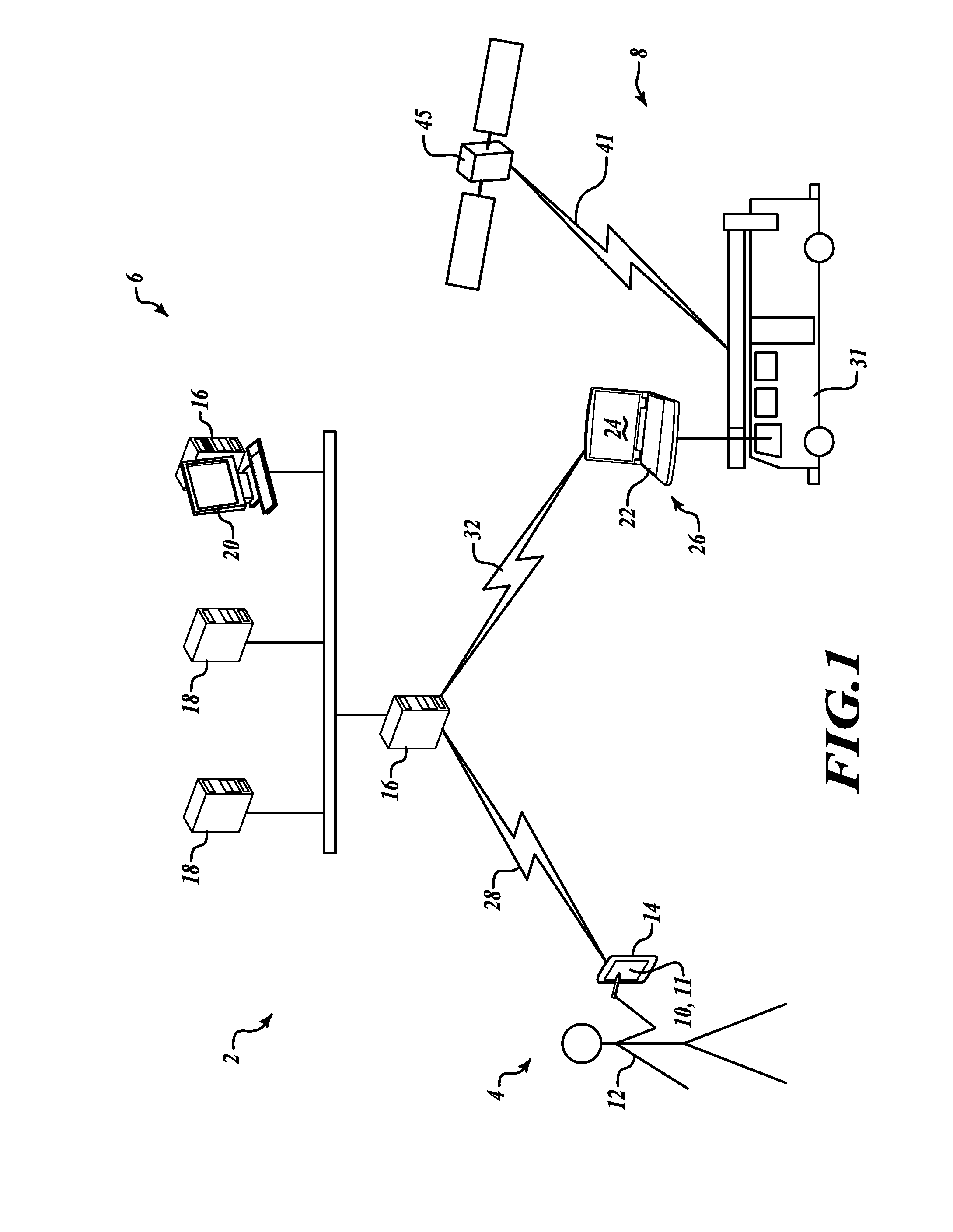
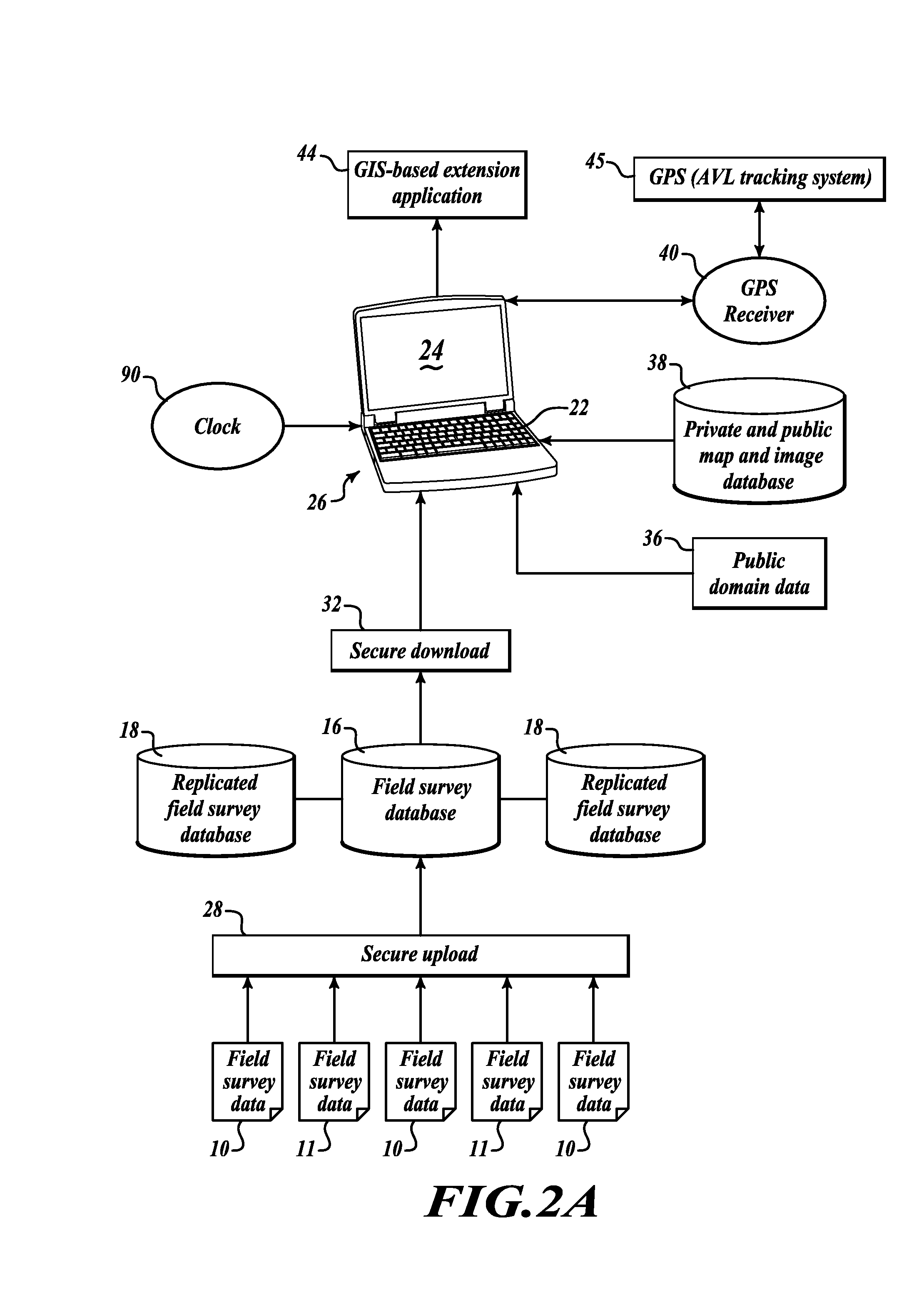
[0024]Responder Route and Site-Specific Critical Data System

[0025]FIG. 1 shows an overview of the primary sub-components of the Responder Route and Site-Specific Critical Data System 2: a Field Data Collection System 4, a Database Maintenan...


PUM


Abstract

A route and site-specific critical data system for emergency responders as they travel and approach an incident site, comprising a field survey database, a computer-executable GIS extension application interfaced with said database, a mobile GPS receiver, and a mobile user interface that includes a display screen capable of touch-screen icon selection including through gloved hands. The user interface mounted within one or more response vehicles displays multiple screen images, map-based, and photograph-based information, detailed text narratives and data in real-time along the entire route to an incident site, including past the public/private road intersection.

Description

CROSS REFERENCE TO RELATED APPLICATION[0001]This is the Regular U.S. Patent Application of prior Provisional Patent Application Ser. No. 60 / 858,910 filed Nov. 13, 2006 by the same inventors, entitled “Emergency Response Route Data System”, the priority of which is hereby claimed under 35 USC 119(e), 120, and the disclosure of which is hereby incorporated by reference in its entirety.FIELD OF THE INVENTION[0002]This invention relates generally to the field of emergency response and in particular to an integrated GIS and GPS-based system to meet the unique challenges of first responders in rural areas by providing those responders with critical route and site specific information, including site-specific information past the public / private intersection.BACKGROUND OF THE INVENTION[0003]Rural Fire and Emergency Medical Service (“EMS”) Districts face unique challenges based on their large area and the lack of funds and specialized equipment compared to urban fire districts. Rural fire di...

Claims


Application Information

Patent Timeline
IPC IPC(8): G06Q50/00G01C21/00G01S5/00G06F3/14G01S19/48
CPCG01C15/00G01S19/17G08G1/202G08B25/08G08B27/001G06Q10/047
Inventor NEEDHAM, FRANK A.ANUNDSON, ROBERT L.SMITH, GARY R.GOSCHEN, KAREN F.
Owner NEEDHAM FRANK A
Why Eureka
Try Eureka