

Door Duct Assembly For Refrigerator
- Summary
- Abstract
- Description
- Claims
- Application Information
AI Technical Summary
Benefits of technology
Problems solved by technology
Method used
Image

Examples
Embodiment Construction
[0119]Next, FIGS. 11 and 12 show another embodiment of the present invention. In the present embodiment, for convenience of description, reference numerals increased by one hundred are given to elements corresponding to those of the previous embodiment.
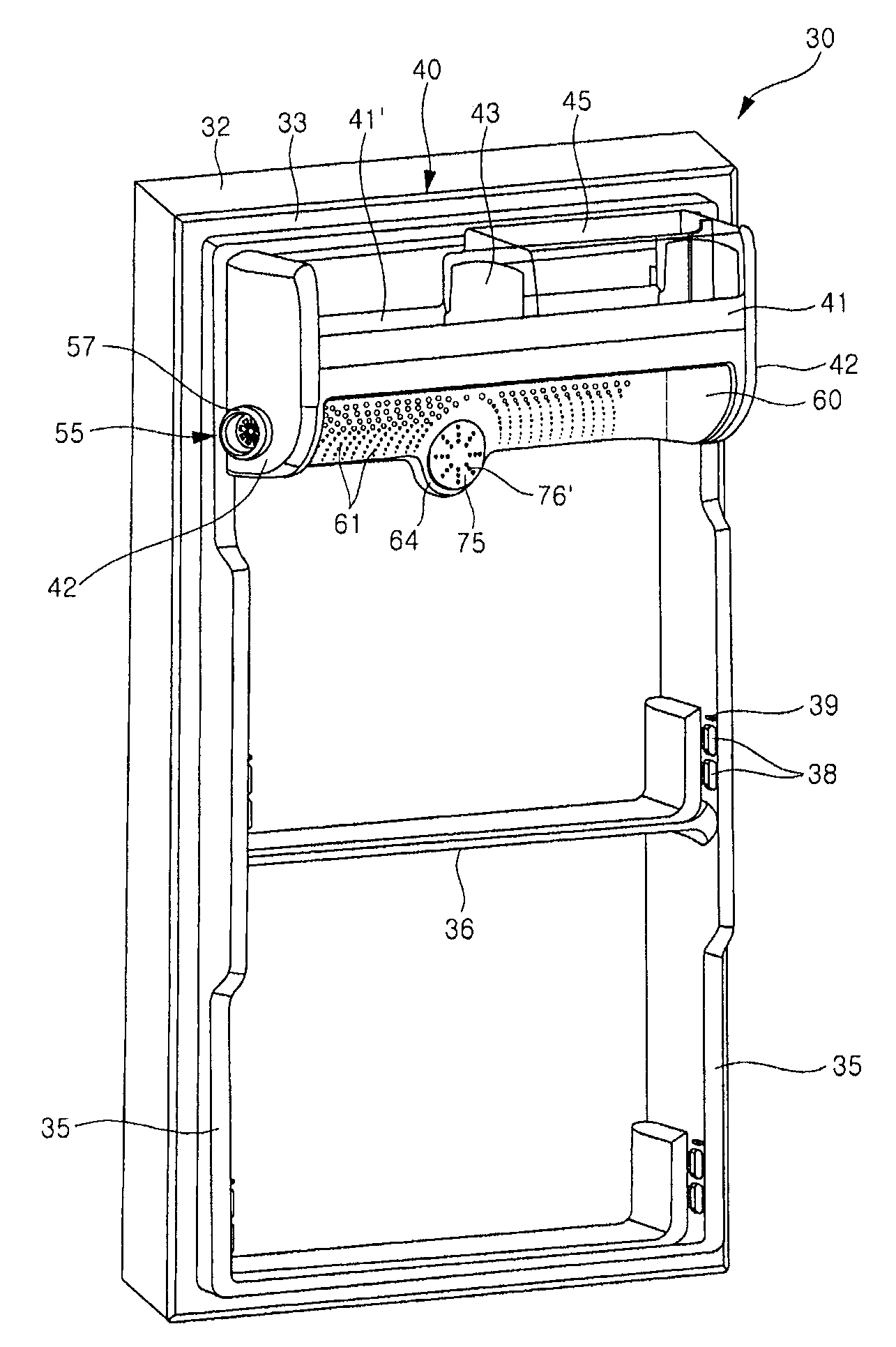
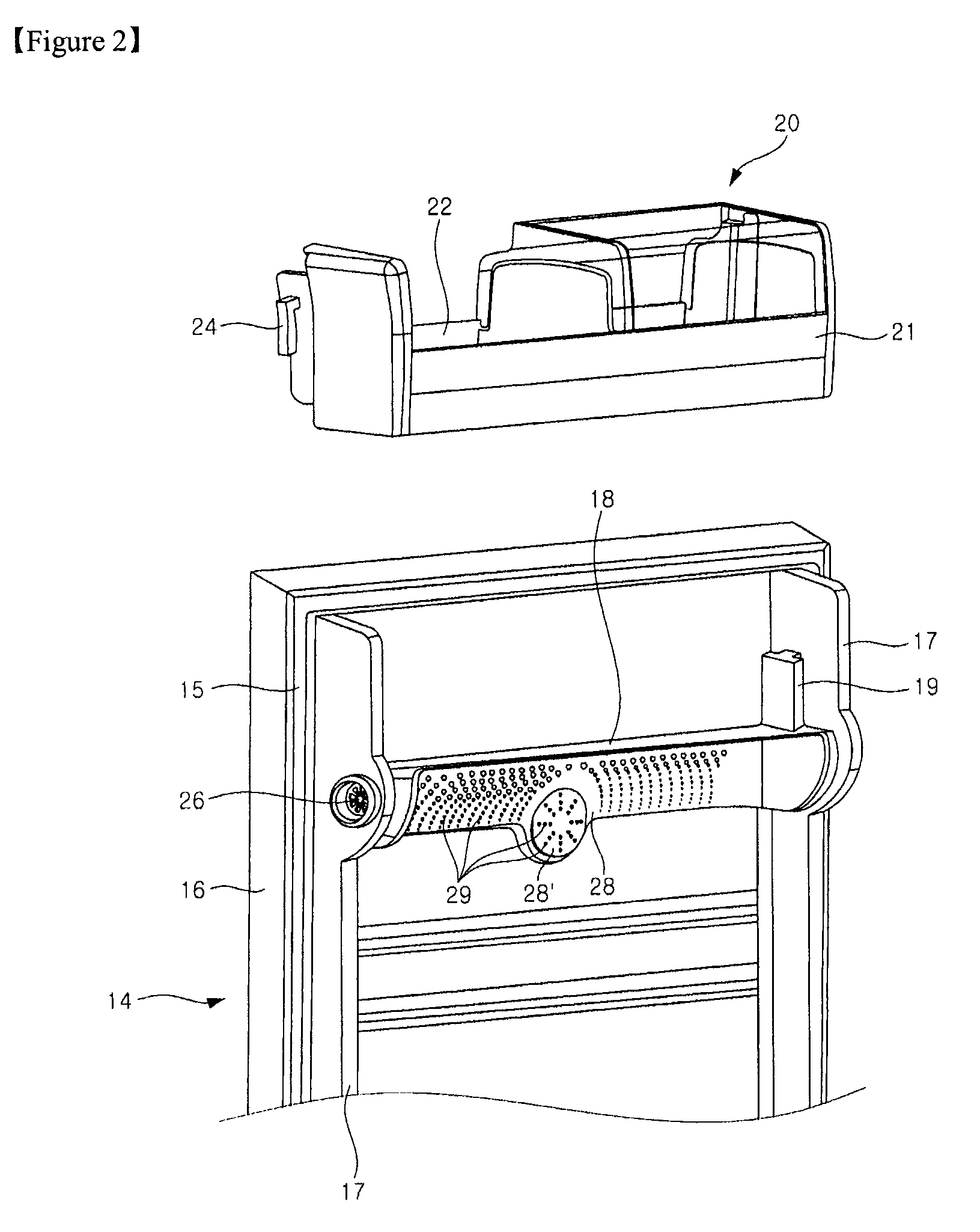
[0120]In the present embodiment, a deodorizer 165 is positioned in a connecting portion 164. That is, while the mounting cover 75 itself functions as a deodorizer in the previous embodiment, the separate deodorizer 165 is used in the present embodiment. Although the deodorizer 165 is formed to have the shape of a quadrangular plate with a plurality of vents in the present illustrated embodiment, it is not necessarily so. The deodorizer 165 may be configured to be inserted into a sidewall 177 of a mounting cover 175, which will be described below.
[0121]In order to install the deodorizer 165, fixing ribs 179′ are formed on a rear surface of a front plate 176 of the mounting cover 175. The fixing ribs 179′ are formed at positions corresp...
PUM
 Abstract
Description
Claims
Application Information