Moving device in a pipe line

US20080115606A1Inactive Publication Date: 2008-05-22HI-LEX CORPORATION

Image

  • Moving device in a pipe line
  • Moving device in a pipe line
  • Moving device in a pipe line

Examples


Embodiment Construction

[0036]Next, referencing the drawings, the embodiments of the moving device in pipe lines of this invention are described.

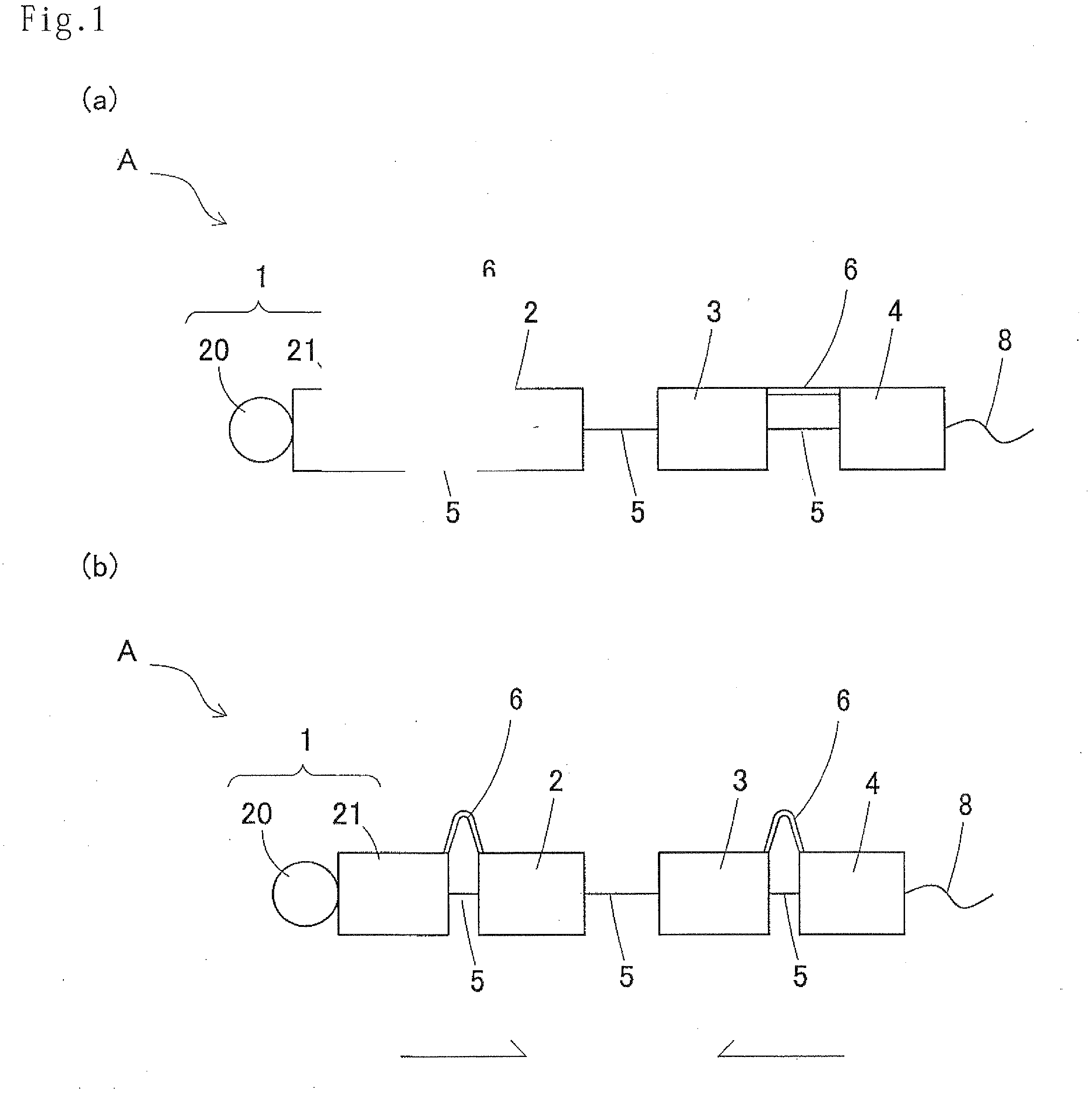
[0037]FIGS. 1a, 1b are pattern diagrams showing the outline of the moving device of this invention.

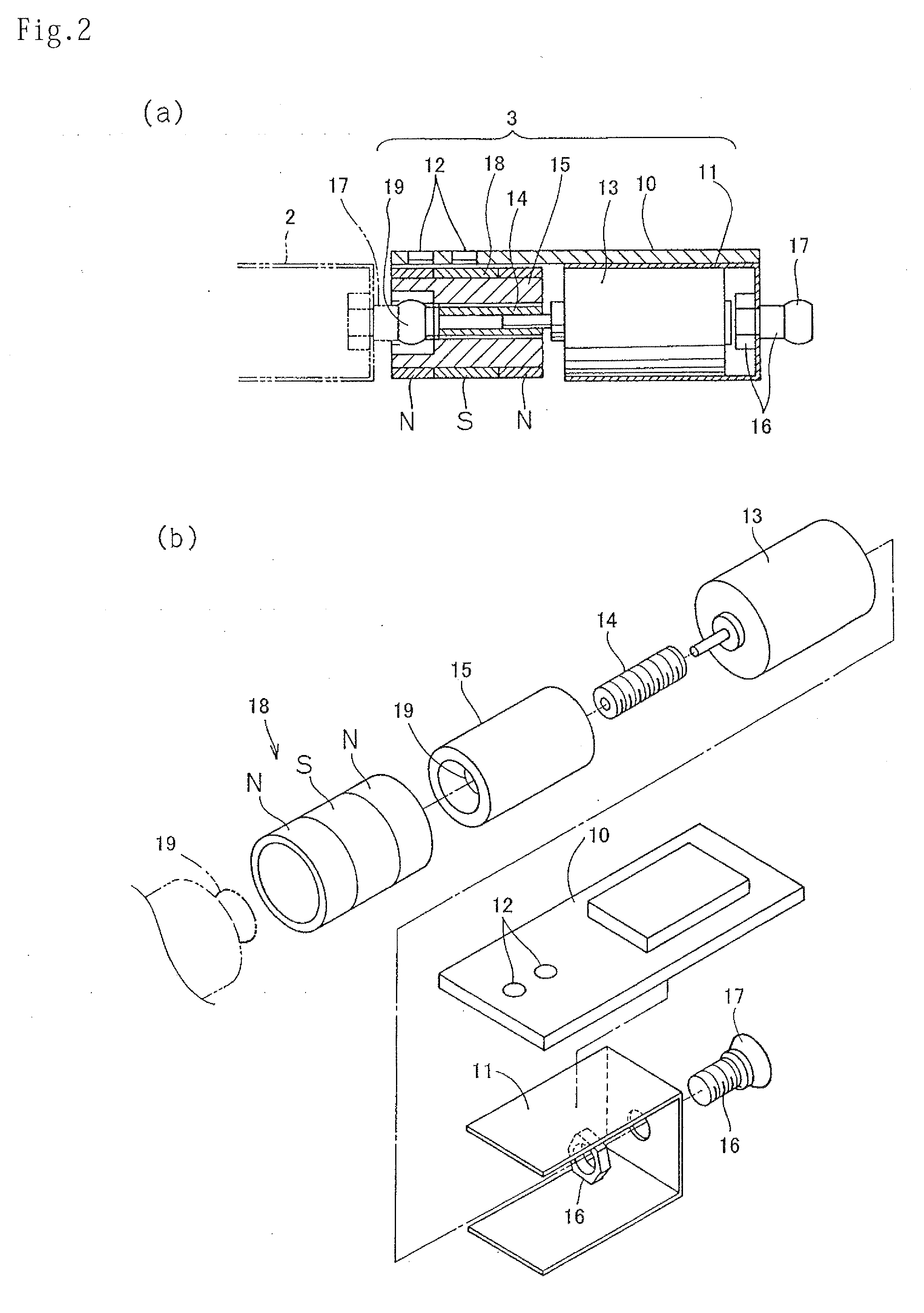
[0038]FIG. 2a is a side cross sectional view showing an embodiment of extendable interconnecting means, FIG. 2b is an exploded perspective view of FIG. 2a.

[0039]FIG. 3 is a rough perspective view of the engaging member.

[0040]FIG. 4a and FIG. 4b are rough drawings showing the aspect of the engaging member being bent.

[0041]FIG. 5a and FIG. 5b are respectively pattern diagrams showing the aspect of the forward movement and the backward movement of the moving device.

[0042]FIG. 6 is a pattern diagram showing the other moving method.

[0043]FIG. 7 is a pattern diagram showing further the other moving method.

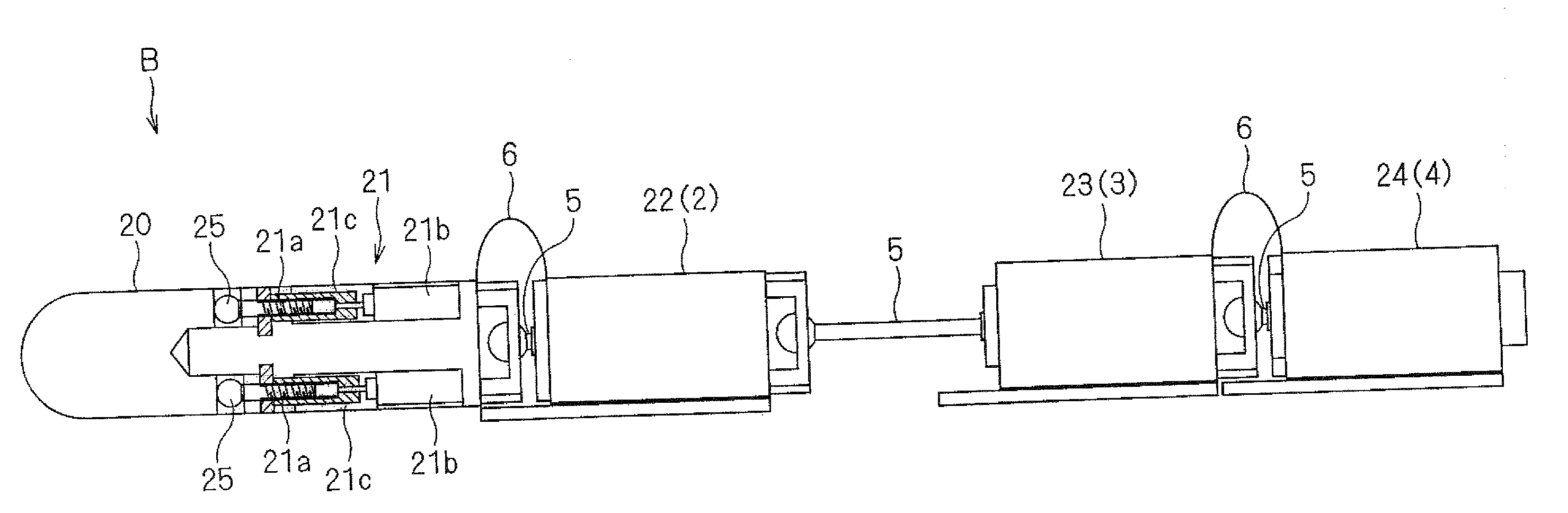
[0044]FIG. 8 is a rough drawing showing an embodiment of the moving device.

[0045]FIG. 9 is a partial cross sectional side view showing the other embodiment of the first ...


PUM


Abstract

A moving device in a pipeline, including: more than three segments, including a front segment, arranged in series; an extendable interconnecting element to connect adjacent segments; and an engaging force changing component to change engaging force of a segment that is to be moved with the inside of the pipeline to a smaller force, smaller than the engaging force of a remaining segment with the inside of the pipeline. The front segment has a head part, a body part, a joint part to turn the head part centering around the body part, and a drive unit to move the head part around the body part. The drive unit have a magnet provided in the head part and an electromagnet provided in the body part.

Description

FIELD OF THE INVENTION[0001]This invention relates to a moving device in a pipe line, for details, to a moving device to carry out move / halt by remote control or autonomously in body cavities or in pipe lines used for conveying various sensors to affected areas or repair portions, and for conveying and discharging medical agents such as curative medicines etc. and repairing agents etc. to repair the repair portions.BACKGROUND ARTS[0002]Patent Document 1: Japanese Published Patent Application No. 2000-219134[0003]Patent Document 2: Japanese Published Patent Application No. 2004-359061[0004]Patent Document 3: Japanese Published Patent Application No. H 7-289504[0005]Patent Document 4: Japanese Published Patent Application No. H 5-344951[0006]Patent Document 5: Japanese Published Patent Application No. 2002-153419[0007]Since a moving device in pipe lines moves in the places where human's hand cannot reach, it must move smoothly in narrow pipe lines to reach a target position and must c...

Claims


Application Information

Patent Timeline
22 May 2008
Publication
US20080115606A1
IPC
A61B1/00
CPC
A61B1/00147; Y10T74/15; A61B1/0055; A61B1/00158; A61B1/00148
Inventors
SUZUKI, KAZUHIRO