Optical tomograph

a tomograph and optical technology, applied in the field of optical tomographs, can solve the problems of reducing productivity, increasing cost, and limited number of data points, and achieve the effects of reducing constraints placed on optical tomographs, simplifying apparatus structure, and improving the resolution of obtained tomographic images

Active Publication Date: 2008-05-22
KK TOPCON
View PDF7 Cites 36 Cited by
  • Summary
  • Abstract
  • Description
  • Claims
  • Application Information

AI Technical Summary

Benefits of technology

[0026]As a further alternative, the optical tomograph of the present invention may be configured such that: at least two of the plurality of light beams emitted from the light source unit have wavelength bands that overlap; and the tomographic image processing means removes interference signals obtained based on the light of the overlapping wavelength band.
[0031]The optical tomograph of the present invention comprises: a light source unit for emitting a plurality of light beams, the wavelengths of each of which are periodically swept within different predetermined wavelength bands respectively; and a plurality of interference light detecting means, each for detecting an interference light beam corresponding to each of the plurality of light beams as an interference signal. Therefore, when the plurality of light beams having different wavelengths are simultaneously irradiated on the measurement target, the interference light beams generated thereby do not mix with each other, and the plurality of interference signals corresponding to each light beam can be obtained simultaneously. Accordingly, the measurement rate can be improved compared to conventional tomographs, and high resolution tomographic images can be obtained at high speed. It is necessary to synchronize and control the light source units of conventional optical tomographs to limit the wavelength of a light beam that enters a detector. However, the optical tomograph of the present invention obviates such control, and the apparatus can be simplified. In addition, each of the interference light detecting means can be of a specialized structure for detecting the interference light beam corresponding to the wavelength band of each light beam. Therefore, the detection accuracy of the interference light detecting means can be improved, thereby improving the resolution of the tomographic image. Further, the need for the components to be employed in the interference light detecting means to detect a wide band light beam is obviated, ad it is only necessary for the components to be capable of detecting the specific wavelength band of each light beam. Accordingly, the constraints placed on the optical tomograph are lessened compared to conventional optical tomographs, general purpose components can be employed, and the structure of the apparatus can be simplified.
[0032]The optical tomograph of the present invention may be configured such that: at least two of the plurality of light beams emitted from the light source unit have discrete wavelength bands and continuous spectra within their respective wavelength bands; and the tomographic image processing means generates a tomographic image of a single portion of the measurement target, employing the interference signals obtained from the at least two light beams. In this case, tomographic images having high image quality equivalent to those obtained by wide band light sources having continuous spectra, or by combinations of light sources that form a continuous spectrum over a wide band can be obtained employing interference signals obtained from a plurality of light beams emitted from the light source unit having a simple structure.
[0034]The optical tomograph of the present invention may be configured such that: at least two of the plurality of light beams emitted from the light source unit have wavelength bands that overlap; and the tomographic image processing means removes interference signals obtained based on the light of the overlapping wavelength band. In this case, the plurality of interference light beams corresponding to the light beams having the overlapping wavelength bands can be positively separated.
[0035]The optical tomograph of the present invention may comprise: a separate light dividing means and a separate combining means are provided for each of the light beams emitted from the light source unit. In this case, the light dividing means and the combining means can be optimized for the wavelength band of each of the light beams, and the resolution of obtained tomographic images can be improved. Further, the need for the components to be employed in the light dividing means and the combining means handle a wide band light beam is obviated, ad it is only necessary for the components to be capable of handling the specific wavelength band of each light beam. Accordingly, the constraints placed on the optical tomograph are lessened compared to conventional optical tomographs, general purpose components can be employed, and the structure of the apparatus can be simplified.

Problems solved by technology

Thereafter, the measuring light beam is irradiated onto a measurement target, and a reflected light beam reflected by the measurement target is caused to interfere with the reference light beam.
Reflected light beams of each wavelength are caused to interfere with reference light beams of each wavelength.
Therefore, the number of data points is limited by the number of elements provided in the detector array.
If the number of elements of the detector array is to be increased in order to increase the number of data points, cost increases, productivity decreases, and measurement rates deteriorate, which is not favorable.
However, if the plurality of light beams having different wavelengths are simultaneously irradiated onto a measurement target, the interference data becomes mixed and undetectable, because the detector is constituted by single elements in conventional SS-OCT apparatuses.
This configuration enables the use of a wide band measuring light beam, but it takes time to irradiate all of the wavelength bands of the measuring light beam, and as a result, a problem arises that the measurement rate decreases.

Method used


Image

  • Optical tomograph
  • Optical tomograph
  • Optical tomograph

Examples


first embodiment

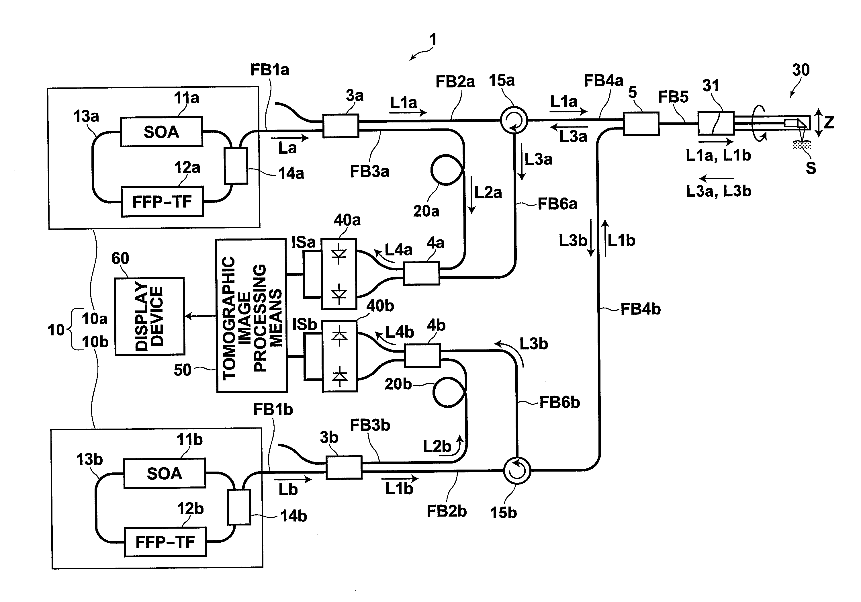
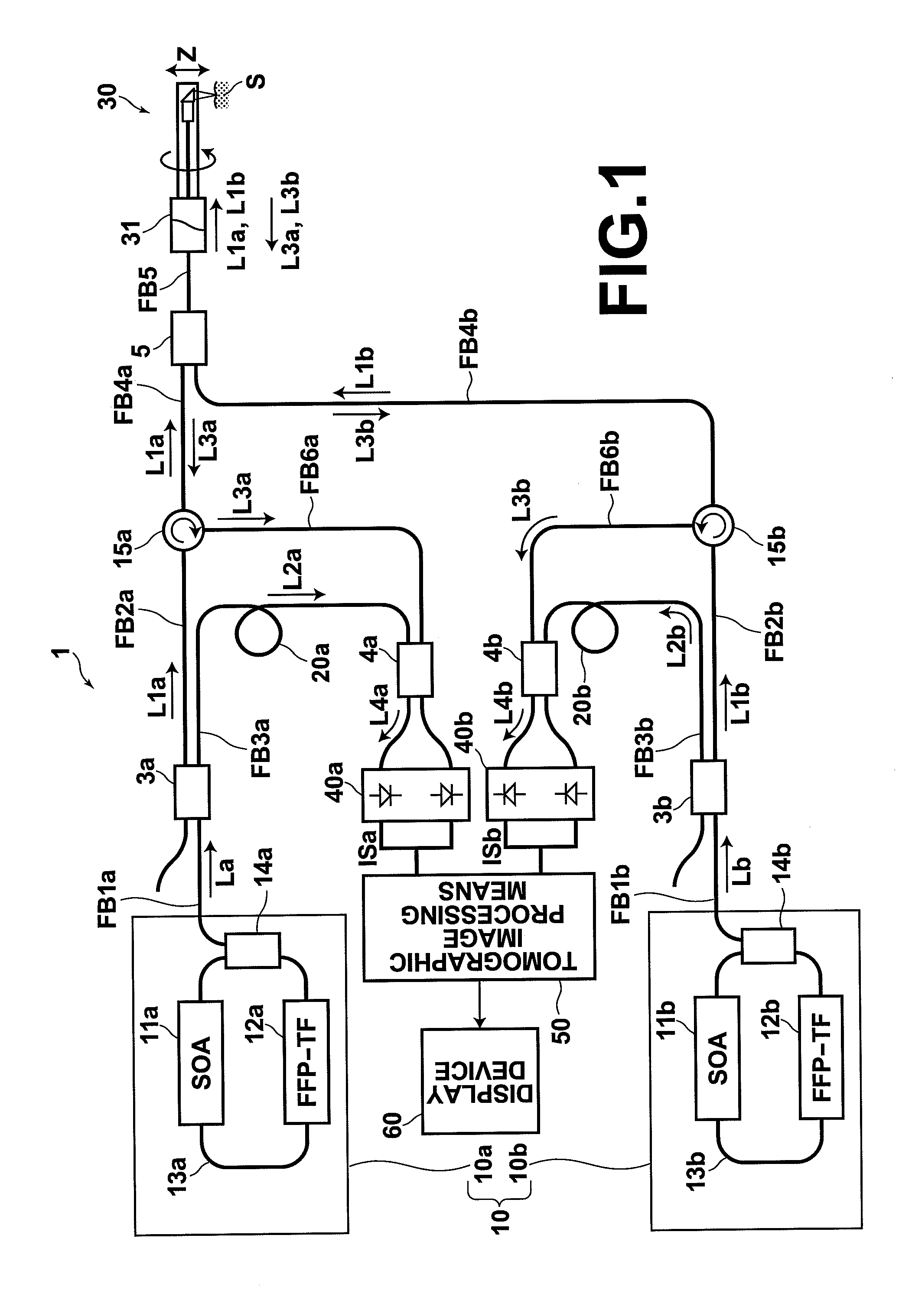
[0056]Hereinafter, optical tomographs according to preferred embodiments of the present invention will be described in detail with reference to the attached drawings. FIG. 1 is a diagram that illustrates the schematic construction of an optical tomograph 1 according to the present invention. The optical tomograph 1 obtains tomographic images of measurement targets such as tissue within body cavities or cells by SS-OCT measurement, using a Mach-Zehnder type interferometer.

[0057]The optical tomograph 1 comprises: a light source unit 10 for emitting light beams La and Lb, the wavelengths of each of which are periodically swept within different predetermined wavelength bands respectively; light dividing means 3a and 3b for respectively dividing the light beams La and Lb into measuring light beams L1a, L1b and reference light beams L2a, L2b; combining means 4a and 4b for combining reflected light beams L3a, L3b, which are the measuring light beams L1a and L1b reflected by a measurement t...

second embodiment

[0097]Hereinafter, an optical tomograph 200 according to the present invention will be described with reference to FIG. 7, FIG. 8A, and FIG. 8B. FIG. 7 is a diagram that illustrates the schematic construction of the optical tomograph 200. Note that in FIG. 7, components of the optical tomograph 200 which are the same as those of the optical tomograph 100 of FIG. 1 are denoted with the same reference numerals, and that detailed descriptions thereof will be omitted, insofar as they are not particularly necessary. The optical tomograph 200 of FIG. 7 differs from the optical tomograph 100 of FIG. 1 in the wavelength bands of the light beams LSa and LSb emitted by the light source 10, and in that optical filters 201a and 201b are provided. Hereinafter, a description will be given mainly regarding the differences between the optical tomograph 200 and the optical tomograph 100.

[0098]The wavelengths of the light beams LSa and LSb emitted by the light source unit 10 of the optical tomograph ...

third embodiment

[0110]Next, an optical tomograph 300 according to the present invention will be described with reference to FIG. 9. FIG. 9 is a diagram that illustrates the schematic construction of the optical tomograph 300. Note that in FIG. 9, components of the optical tomograph 300 which are the same as those of the optical tomograph 100 of FIG. 1 are denoted with the same reference numerals, and that detailed descriptions thereof will be omitted, insofar as they are not particularly necessary. The optical tomograph 300 is an SS-OCT apparatus that employs a Mach-Zehnder interferometer. The optical tomograph 300 differs from the optical tomograph 100 in that the combining / dividing means 5 is provided upstream of the interferometer. Hereinafter, a description will be given mainly regarding the differences between the optical tomograph 300 and the optical tomograph 100.

[0111]In the optical tomograph 300, the light beam La emitted by the light source 10a propagates through the optical fiber FB1a, a...


PUM


Abstract

An optical tomograph is equipped with: a light source unit for emitting a plurality of light beams, the wavelengths of which are swept within different predetermined wavelength bands respectively with the same period; light dividing means, for dividing each light beam into a measuring light beam and a reference light beam; combining means, for combining reflected light beams, which are the measuring light beams reflected by a measurement target when the measuring light beams are irradiated thereon, with the reference light beams; interference light detecting means, for detecting an interference light beam, which is formed by the reflected light beam and the reference light beam being combined by the combining means, for each of the light beams as an interference signal; and tomographic image processing means, for generating a tomographic image of the measurement target employing the plurality of interference signals detected by the interference light detecting means.

Description

BACKGROUND OF THE INVENTION[0001]1. Field of the Invention[0002]The present invention relates to an optical tomograph that obtains optical tomographic images by OCT (Optical Coherence Tomography) measurement.[0003]2. Description of the Related Art[0004]Conventionally, optical tomographs that utilize OCT measurement are used to obtain optical tomographic images of living tissue. In these optical tomographs, a low coherence light beam emitted from a light source is divided in to a measuring light beam and a reference light beam. Thereafter, a reflected light beam, which is the measuring light beam reflected or backscattered by a measurement target when the measuring light beam is irradiated onto the measurement target, is combined with the reference light beam. Tomographic images are obtained, based on the intensity of a coherent light beam obtained by combining the reflected light beam and the reference light beam. Hereinafter, the light beam, which is reflected or backscattered by t...

Claims


Application Information

Patent Timeline
Patent Type & Authority Applications(United States)
IPC IPC(8): G01B9/02
CPCG01N21/4795G01B9/02004G01B9/02007G01B9/02027G01B2290/45G01B9/02091G01B9/02069G01B9/02087G01B9/02057
Inventor TERAMURA, YUICHIAKAHORI, SADATOKUROIWA, KARIN
Owner KK TOPCON
Why Eureka
Try Eureka