Combustion control for a gas turbine

a gas turbine and combustion control technology, applied in the direction of machines/engines, mechanical equipment, lighting and heating apparatus, etc., can solve the problems of increasing the risk of engine failure, so as to reduce the amplitude of combustion instabilities

Inactive Publication Date: 2008-05-22
ROLLS ROYCE PLC
View PDF17 Cites 13 Cited by
  • Summary
  • Abstract
  • Description
  • Claims
  • Application Information

AI Technical Summary

Benefits of technology

[0007]It is an object of the present invention to seek to provide an improved method and apparatus for reducing the amplitude of combustion instabilities.

Problems solved by technology

A significant limiting factor in the development and introduction of ultra-low NOx combustors is a propensity to combustion instabilities at lean mixture fractions.
At lean air / fuel ratios (AFR) slight changes in the AFR can lead to large changes in heat release which can lead to an audible rumbling sound that may cause passenger discomfort or fatigue failure of engine components, depending on the frequency and amplitude of the instability.
Modulation of the fuel is achieved through the use of a valve which, by operating at a frequency close to the combustor oscillation frequency, is subject to a significant amount of valve wear that raises reliability concerns and adds additional complexity to the system.

Method used


Image

  • Combustion control for a gas turbine
  • Combustion control for a gas turbine
  • Combustion control for a gas turbine

Examples


Embodiment Construction

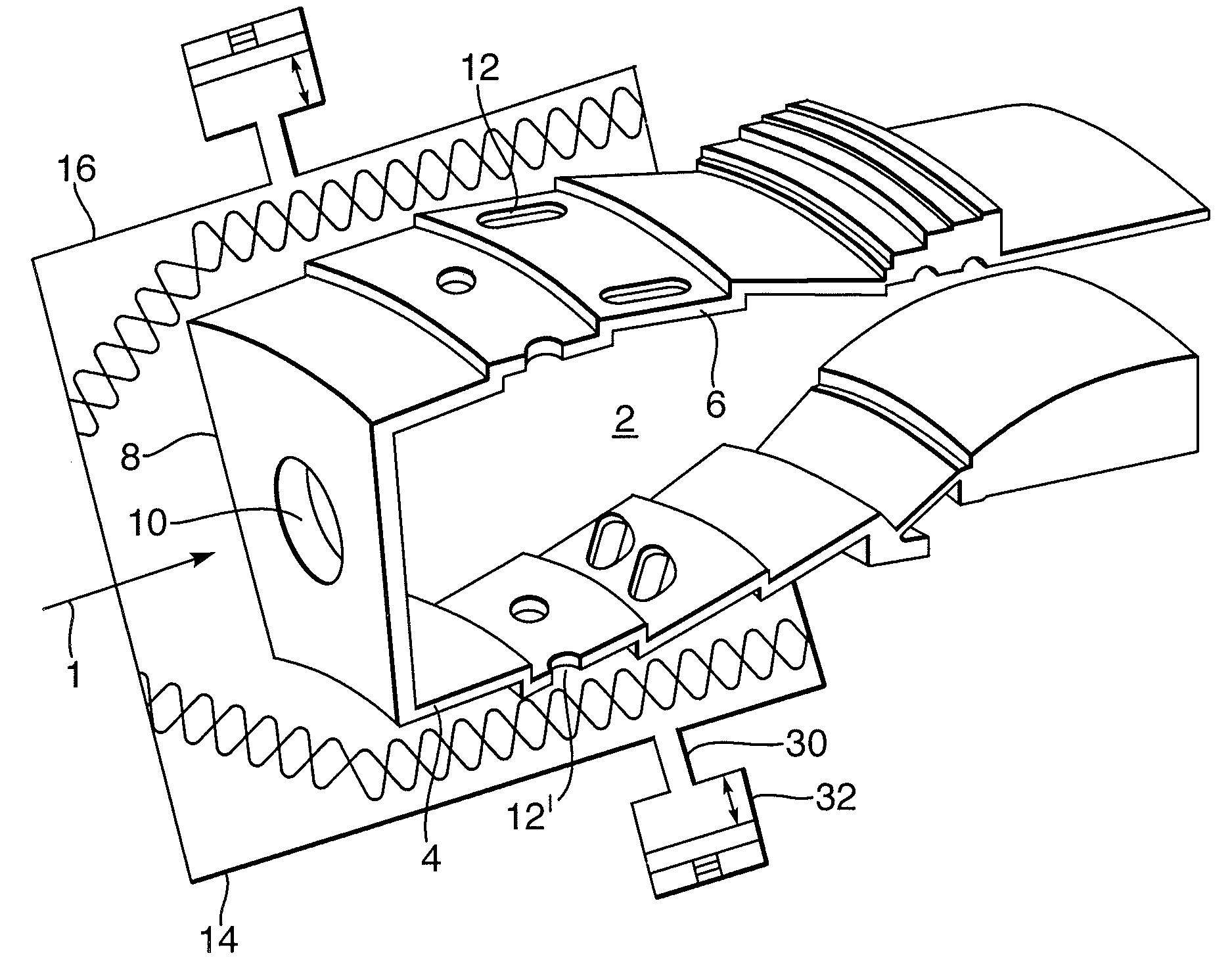
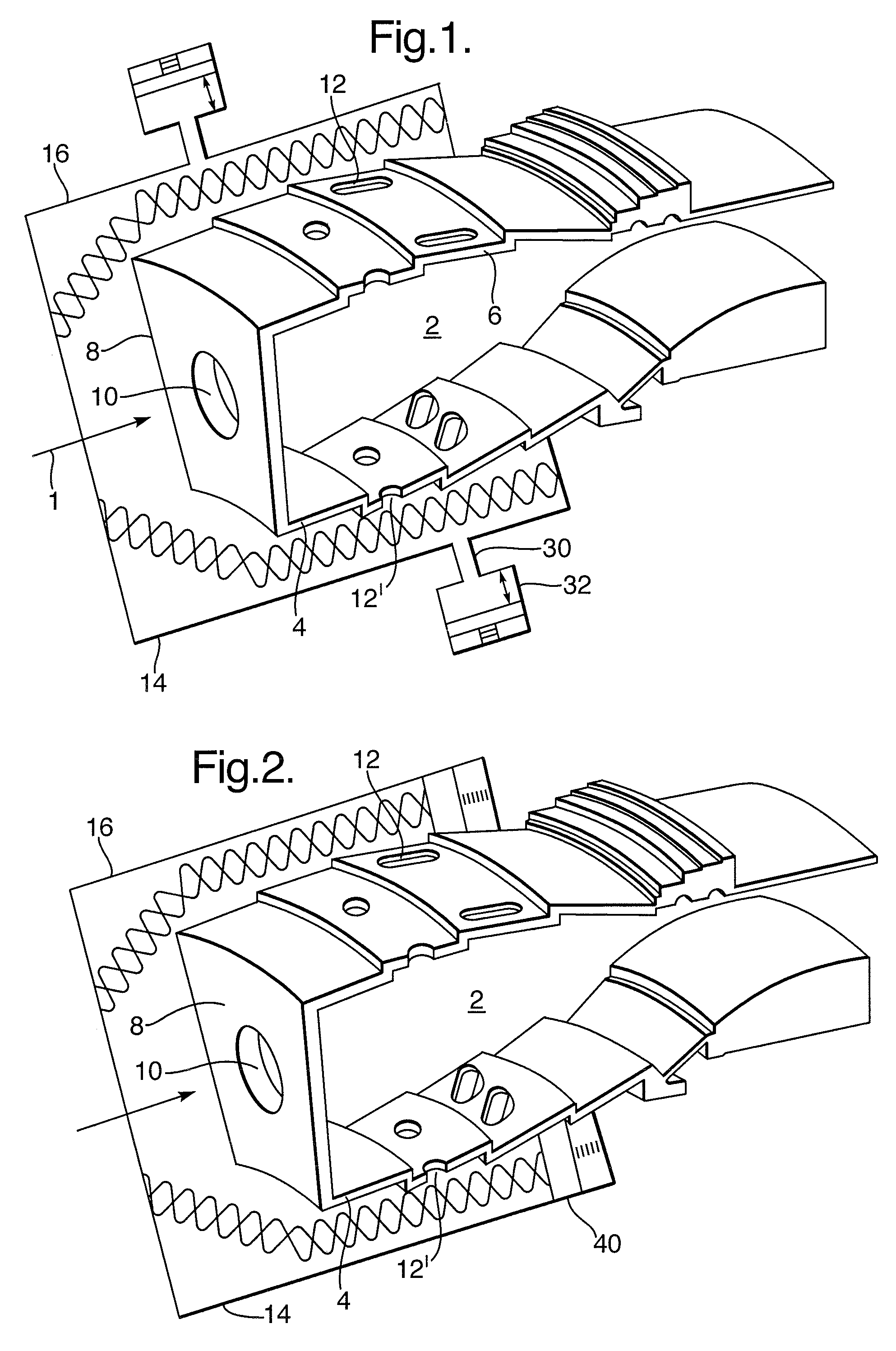
[0030]FIG. 1 depicts an annular combustion chamber 2 which consists of a single annular flame tube contained between a radially inner combustor wall 4 and a radially outer combustor wall 6. A stream of compressed air is supplied to the combustor generally in the direction of arrow 1. The upstream end of the chamber is bounded by a combustor head 8 which contains a circular array of apertures 10 which are circumferentially spaced (a single aperture is shown for clarity). The downstream end of the combustor leads to high pressure turbine nozzle guide vanes and then on to a turbine in the gas turbine engine.

[0031]The aperture 10 in the combustor head accepts a fuel injector (not shown), which injects fuel into the combustion chamber 2. Each fuel injector receives air from an upstream compressor which it mixes with the fuel to create a combustible mixture which is ignited either by an igniter, or by fuel burning in the combustion chamber. Ignited fuel generates a hot combustion gas at a...


PUM


Abstract

A method for controlling instability in a combustion system comprising a combustion chamber and a passage external of the combustion chamber which supplies a secondary non-combustible fluid to the combustor chamber. The passage external to the combustion chamber is arranged such that the phase of perturbations in the mass flow of the secondary non-combustible fluid in the passage acts to reduce the amplitude of unsteady instability in the combustor chamber. Furthermore, the geometry of the external passage may be actively adjusted to tune the system if the frequency of the unstable instability differs from that for which the combustor was originally designed to attenuate.

Description

CROSS-REFERENCE TO RELATED APPLICATION[0001]This application is entitled to the benefit of British Patent Application No. GB 0621001.7 filed on Oct. 21, 2006.FIELD OF THE INVENTION[0002]The invention relates to combustor systems for gas turbine engines.BACKGROUND OF THE INVENTION[0003]A significant limiting factor in the development and introduction of ultra-low NOx combustors is a propensity to combustion instabilities at lean mixture fractions. At lean air / fuel ratios (AFR) slight changes in the AFR can lead to large changes in heat release which can lead to an audible rumbling sound that may cause passenger discomfort or fatigue failure of engine components, depending on the frequency and amplitude of the instability.[0004]Combustion instabilities are currently addressed in two ways: actively and passively. In an active control method the fuel supply is modulated at a frequency that is similar to that of the instability to be controlled. Modulation of the fuel is achieved through...

Claims


Application Information

Patent Timeline
Patent Type & Authority Applications(United States)
IPC IPC(8): F03B15/06F23M20/00
CPCF23M20/005F23R2900/00013F23R3/04
Inventor ARTHUR, DAVID MATTHEWDOWLING, ANN PATRICIA
Owner ROLLS ROYCE PLC
Why Eureka
Try Eureka