Multi-Axial Spinal Fixation System

a multi-axial, spinal fixation technology, applied in the direction of ligaments, prostheses, osteosynthesis devices, etc., can solve the problems of affecting the overall appearance and profile of the components

Active Publication Date: 2008-05-22
SPINEWAVE
View PDF87 Cites 102 Cited by
  • Summary
  • Abstract
  • Description
  • Claims
  • Application Information

AI Technical Summary

Benefits of technology

[0017]One benefit of the present invention is that it provides for solid anchoring between a spinal rod and a bone engaging fastener at variable spherical angles. A further benefit is that a common clamping element is provided to clamp the spinal rod and fix the angular position of the anchor device. Yet another benefit resides in one aspect of the anchor device that reduces the overall prominence and profile of the components of the device. Other benefits of the invention can be discerned from the following written description and accompanying figures.

Problems solved by technology

Early rod-type spinal fixation systems incorporated anchor devices that permitted very limited relative orientations of the rod relative to the fixation element.
One detriment of this system is that the spinal rod must be threaded in order to accept the compression nuts, which has a tendency to weaken the spinal rod in the face of severe spinal loads.
This apparatus is bulky and difficult to manipulate given the external sliding locking mechanism.

Method used


Image

  • Multi-Axial Spinal Fixation System
  • Multi-Axial Spinal Fixation System
  • Multi-Axial Spinal Fixation System

Examples


Embodiment Construction

[0040]For the purposes of promoting an understanding of the principles of the invention, reference will now be made to the embodiments illustrated in the drawings and described in the following written specification. It is understood that no limitation to the scope of the invention is thereby intended. It is further understood that the present invention includes any alterations and modifications to the illustrated embodiments and includes further applications of the principles of the invention as would normally occur to one skilled in the art to which this invention pertains.

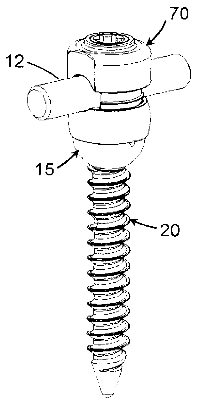
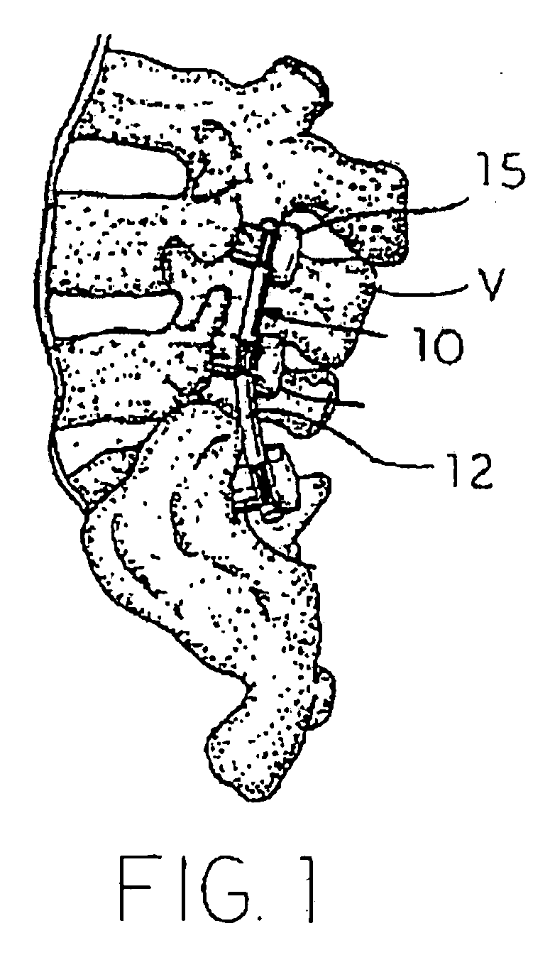
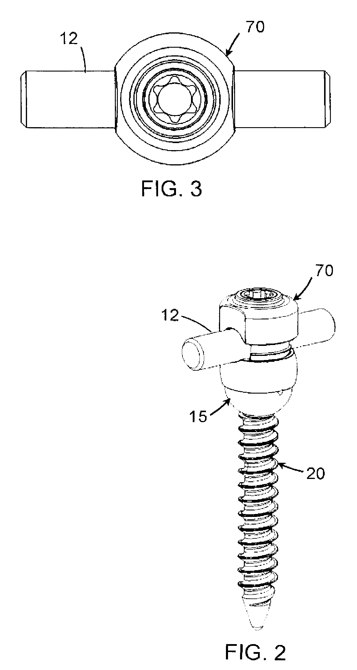
[0041]The present invention contemplates a spinal fixation system, such as the system 10 depicted in FIG. 1. As is known in the art, the fixation system 10 spans between successive vertebrae of the spine. An elongated member, such as rod 12, extends along the length of the spine and provides an anchor point for connecting each vertebra to the rod. The rod is typically contoured to approximate the normal curvatur...


PUM


Abstract

A spinal fixation system includes an elongated rod sized to extend between at least two vertebrae and a number of anchor devices for anchoring the rod to the spine. The anchor devices include a bone engaging fastener having a head defining a spherical socket. A ball insert is configured to be placed within the socket and rotated so that a spherical surface of the ball insert is juxtaposed with the spherical surface of the socket. The insert has a first dimension less than the socket opening and a second dimension that upon rotation causes the insert to be captively retained in the socket. The anchor device further includes a yoke defining a yoke channel for receiving the rod and including a stem that is engaged to the ball insert when the insert is captured within the socket. A sleeve is disposed between the yoke channel and the fastener head for supporting the rod thereon. A set screw is threaded into the yoke channel for clamping the rod against the sleeve. The set screw further operates to draw the ball insert into clamped engagement within the socket.

Description

BACKGROUND [0001]The present invention relates to spinal fixation systems and particularly to an anchor device that incorporates multi-axial fixation to the spine.[0002]Several techniques and systems have been developed for correcting and stabilizing injuries to or malformation of the spine. In one type of system, an elongated member such as a bendable rod is disposed longitudinally along a length of the spine, spanning two or more vertebral levels. In certain applications, the rod is bent to correspond to the normal curvature of the spine in the particular region being instrumented, such as the normal kyphotic curvature of the thoracic region or the lordotic curvature of the lumbar region. In accordance with such a system, the rod is engaged to various vertebrae along a length of the spinal column by way of a number of anchor devices that utilize a variety of fixation elements configured to engage specific portions of the vertebra and other bones. For instance, one such fixation el...

Claims


Application Information

Patent Timeline
Patent Type & Authority Applications(United States)
IPC IPC(8): A61B17/58
CPCA61B17/7032A61B17/7037A61B17/7082A61B17/88A61B17/8875B25B23/105A61B17/7086
Inventor POTASH, ROBERTJAMES, ANTHONY
Owner SPINEWAVE
Why Eureka
Try Eureka