
Osteotomy implant

a technology of osteotomy and implant, which is applied in the field of surgical devices, can solve the problems of excessive wear of knee cartilage, soft tissue irritation, patient discomfort during recovery, etc., and achieve the effect of reducing the prominence of any implant par

Active Publication Date: 2016-10-06
RIOS MEDICAL +1
View PDF6 Cites 2 Cited by
  • Summary
  • Abstract
  • Description
  • Claims
  • Application Information

AI Technical Summary

Benefits of technology

The invention is about a new implant used in osteotomy surgery. The implant is designed to minimize damage to the growth of bone in the surgery and reduce the likelihood of complications.

Problems solved by technology

Due to for example arthritic damage on one side of the knee, born misalignment, or trauma injury, this alignment can be disturbed and cause excessive wear of the knee cartilage, known as knee-arthroses.
Despite these advantages, complications are often associated with this technique, which often causes the patient discomfort during recovery.
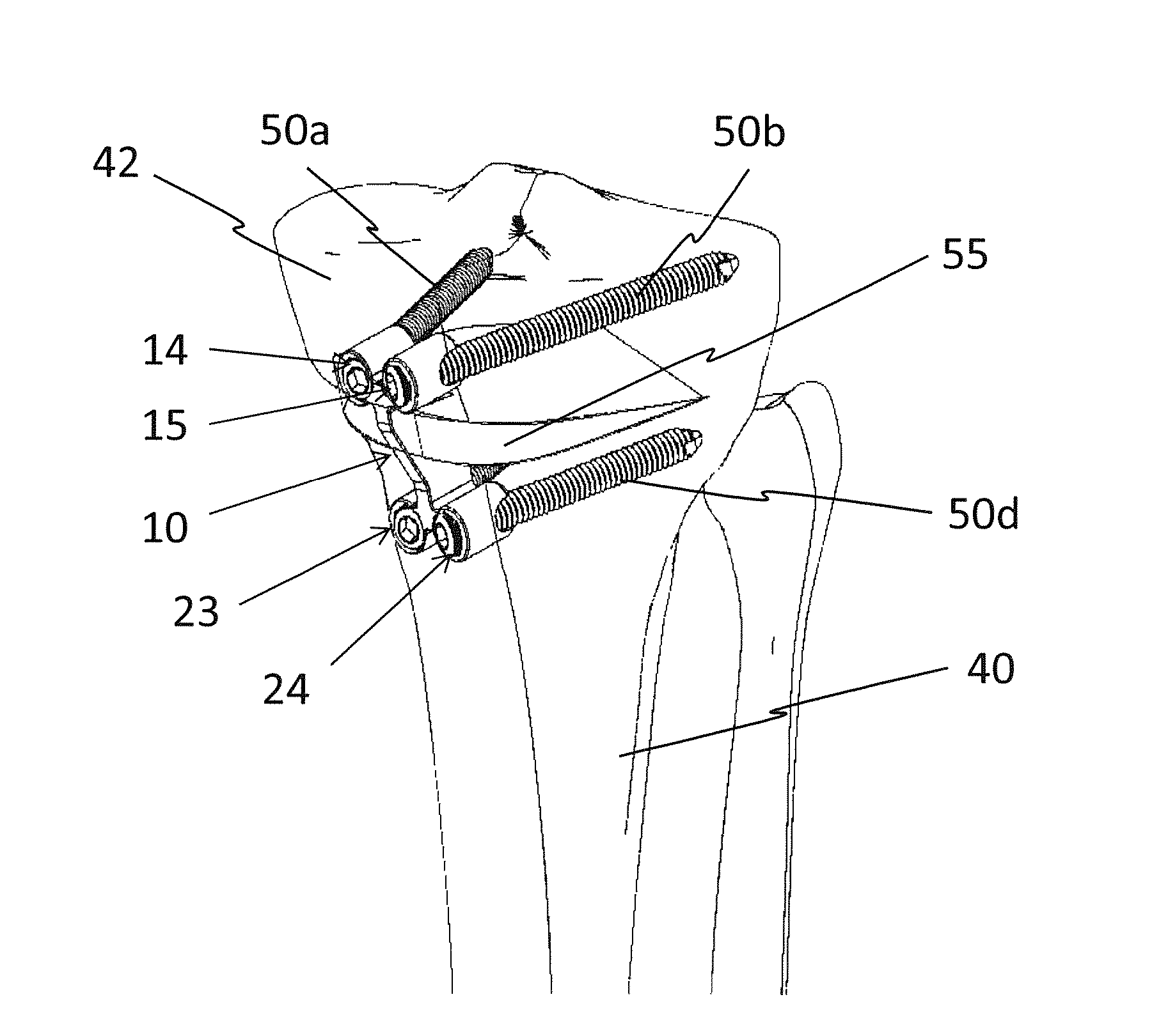
One of the more important causes of pain is the prominence of plates and screws laying on top of the bone, causing soft tissue irritation.
One major drawback of the apparatus as disclosed in U.S. Pat. No. 8,137,406 B2 is that the osteotomy plate spans a large section of the wedge like opening of the bone, thereby preventing bone ingrowth over this large section.

Method used


Image

  • Osteotomy implant
  • Osteotomy implant
  • Osteotomy implant

Examples


second embodiment

[0087]FIGS. 7a to 7c show an osteotomy implant 10 according to the present invention. The middle strut portion 30 has different widths W1, W2 on its two sides. The side of the middle strut portion 30 which is intended to be arranged within the bone has a second width W2 which is smaller than the first width W1 on the front 31, which is intended to be arranged parallel to the cortex of the bone. This feature is recognizable by comparing FIG. 7a, which shows the osteotomy implant 10 from the front 31 and FIG. 7b which shows the osteotomy implant 10 from the side intended to be arranged within the bone.

[0088]Further, the four cylindrical bodies 12, 13, 21, 22 are tapered towards their end which is intended to be inserted within the bone, giving the four cylindrical bodies 12, 13, 21, 22 a slight conical shape, as may be seen by the side view of the osteotomy implant 10 as shown in FIG. 7c. Use of tapered cylindrical bodies 12, 13, 21, 22 facilitates the insertion of the osteotomy impla...

third embodiment

[0089]FIGS. 8a and 8b show an osteotomy implant 10 according to the present invention. This embodiment corresponds largely to the embodiment as shown in FIG. 2. However, as shown in FIG. 8a, an additional fifth aperture 70 is arranged in the middle strut portion 30. The fifth aperture 70 has a central axis 72 which includes an acute angle to the front 31 of the middle strut portion 30. As seen in FIG. 8b, the fifth aperture 70 may receive a compression screw 71. The compression screw 71 helps establishing a compression force over the osteotomy opening 41, which helps the primary and secondary stability of the implant.

[0090]In another alternative embodiment, the instruments for implantation and the osteotomy implants are part of a single use kit. Different sizes of implants will require different bone preparation devices that correspond with the shape of the implant. An exemplary single use kit comprises combinations of the following components:[0091]an osteotomy implant 10;[0092]bon...


PUM


Abstract

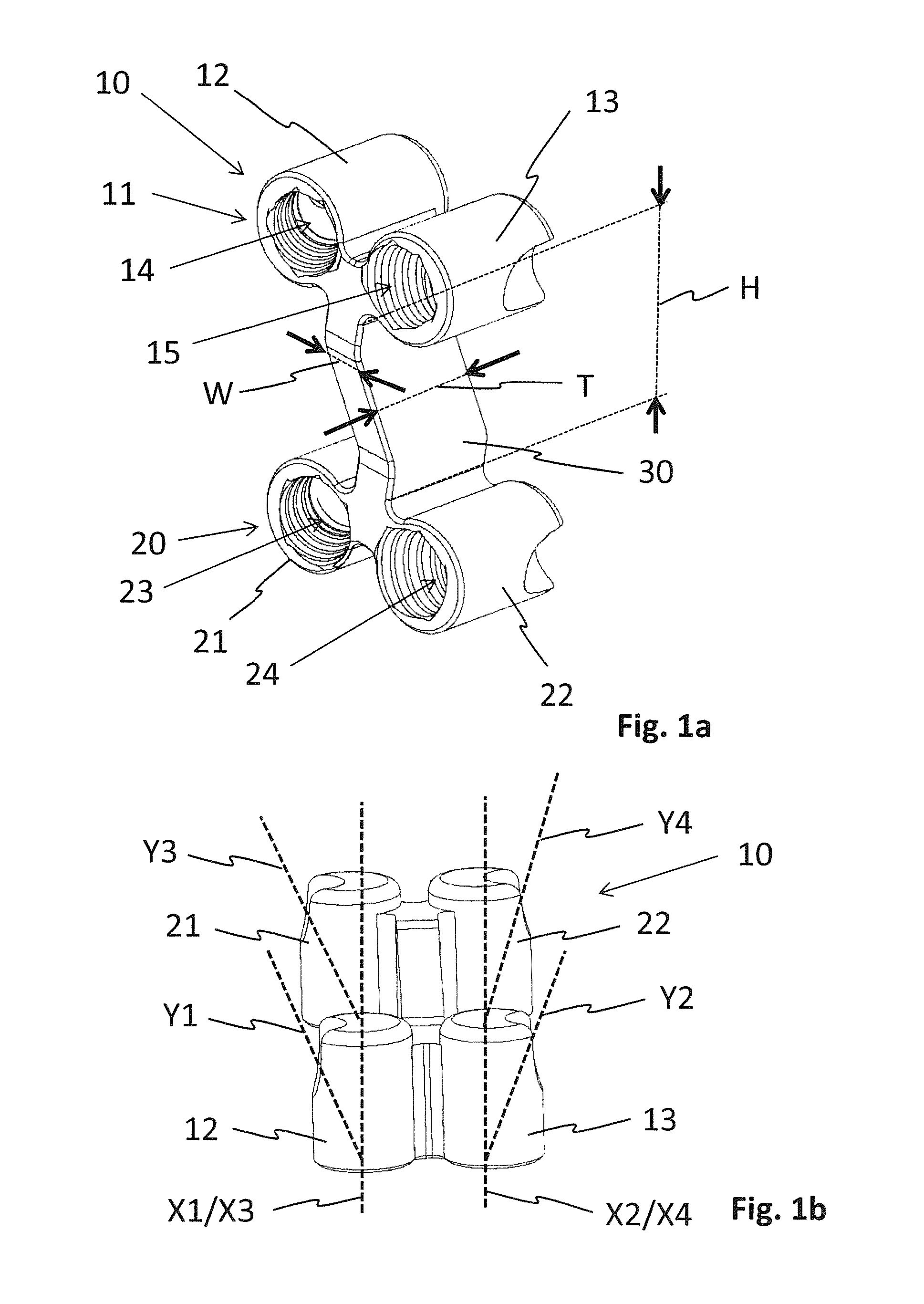
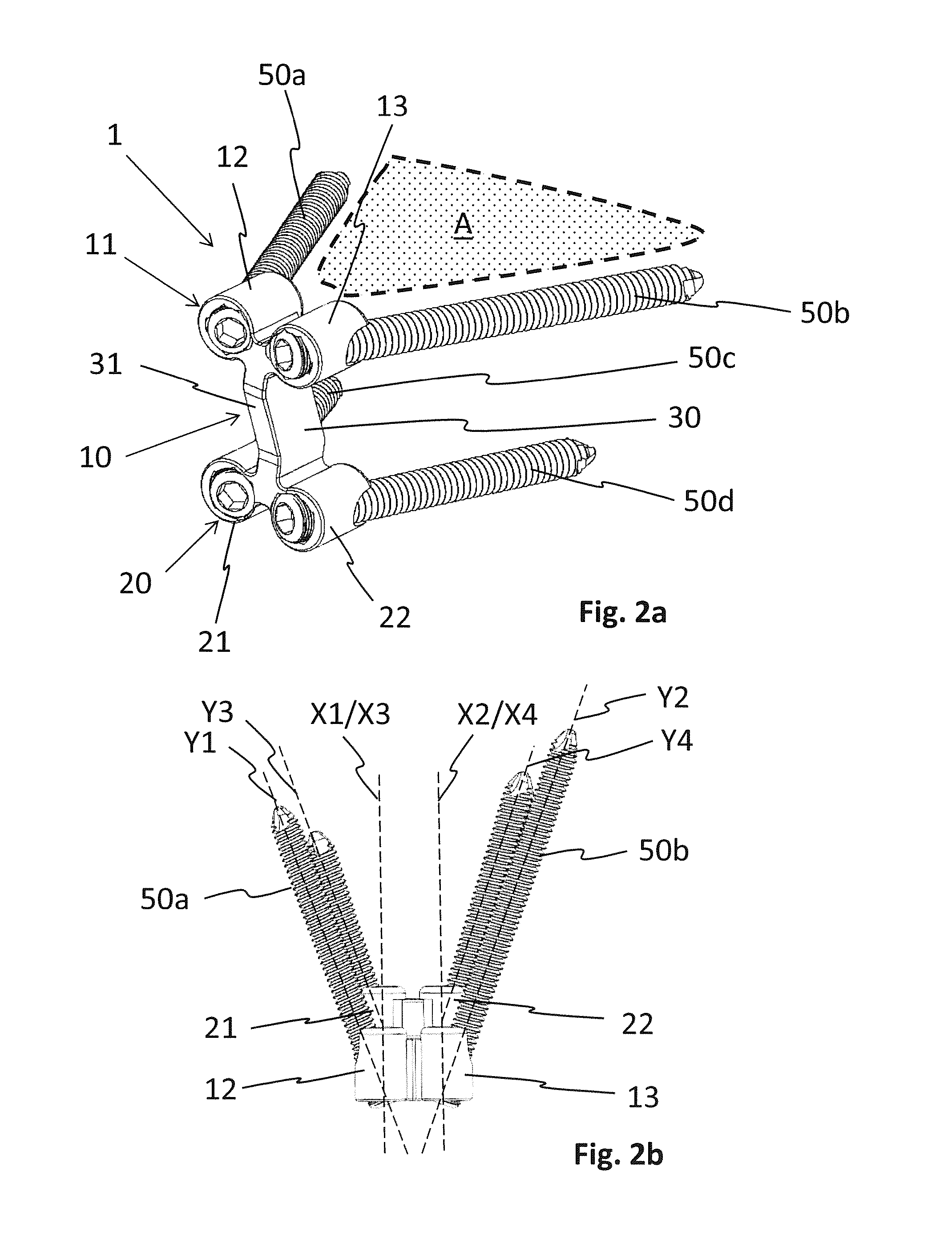
The present inventions relates to an osteotomy implant for bridging an osteotomy opening or resection in a target bone in a substantially countersunk manner. The osteotomy implant comprises a proximal portion with at least one aperture for receiving at least one bone fixation element and a distal portion with at least one aperture for receiving at least one bone fixation element. At least one middle strut portion connects said proximal portion with said distal portion. Said at least one middle strut portion has a width which is equal to or smaller than a thickness of said at least one middle strut portion.

Description

TECHNICAL FIELD[0001]The invention relates to surgical devices for performing opening wedge and closing wedge osteotomies of the knee.BACKGROUND ART[0002]Knee osteotomy is a surgical method used to realign the Mikulicz-line of the large joints of the lower limb, namely the hip, knee and ankle. With normal axial alignment of the limb the centre of the hip, the inter-condylar eminence of the tibial plateau and the centre of the ankle joint are in one line, the mechanical axis of the lower limb.[0003]Due to for example arthritic damage on one side of the knee, born misalignment, or trauma injury, this alignment can be disturbed and cause excessive wear of the knee cartilage, known as knee-arthroses.[0004]The purpose of the knee osteotomy surgical technique is to re-divide the forces in the knee in an early stage away from the damaged area to the opposite healthier side of the knee. Forces stemming from the patient's body weight and muscular reaction forces are better spread over the kn...

Claims


Application Information

Patent Timeline
Patent Type & Authority Applications(United States)
IPC IPC(8): A61B17/80A61B17/16A61B17/15
CPCA61B17/8095A61B17/154A61B2017/00707A61B17/1675A61F2002/4687A61B17/157A61B17/14A61B17/158A61B17/1657A61B17/1659A61B17/1677A61B17/1764A61B17/683A61B17/8625A61F2/28A61B17/151
Inventor PAVLOV, PAULOVERES, TOM
Owner RIOS MEDICAL
Learn More