Mop

A mop and mop rod technology, applied in the field of mop for cleaning, can solve problems such as poor labor-saving effect, poor operating experience, and waste of water squeezing force

Pending Publication Date: 2020-10-20
王火德
View PDF4 Cites 2 Cited by
  • Summary
  • Abstract
  • Description
  • Claims
  • Application Information

AI Technical Summary

Problems solved by technology

At present, the collodion head mops on the market basically only use a part of the surface of the collodion head for cleaning, and this part can be divided into two small cleaning surfaces at the front and back for two rotations. The utilization rate of the cleaning surface is low and the cleaning surface The number of switchable uses is less
[0004] The Chinese invention patent with the notification number CN102764103B "Cleaning parts installation frame and mop for mop" discloses a mop with a rotating collodion head. The collodion head is connected to the mop rod through a shaft. The utilization rate of the surface, but the water squeezing device has many parts, is not compact, and the labor-saving effect is not good, and the water squeezing force of one

Method used


Image

  • Mop
  • Mop
  • Mop

Examples


Embodiment 1

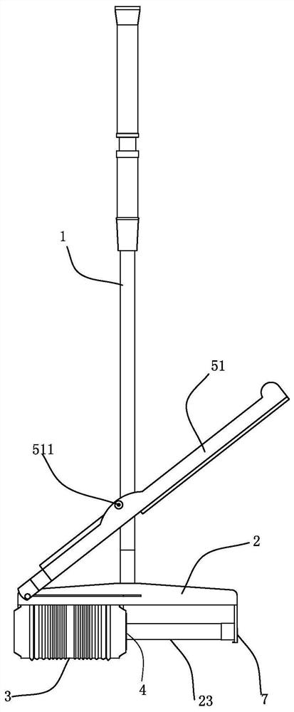
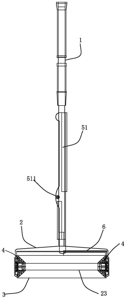
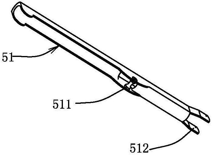
[0057] The present invention relates to a mop, such as Figure 1~2 As shown, it includes a mop rod 1, a mounting frame 2 attached to the lower end of the mop rod, a cleaning piece 3 with at least one end slidable and compressible on the mounting frame 2, and radially deformable cleaning parts located at both ends of the cleaning piece 3. The cover part 4 and the squeeze lever 51 attached to the mop rod 1 and linked with the sliding end of the cleaning part 3 also include an elastic limiting part 7 for limiting the rotation of the cleaning part 3 . The linkage between the water squeezing lever 51 and the cover 4 arranged at the sliding end of the cleaning part 3 is realized through the connecting rod 6, the upper part of the water squeezing lever 51 is exerted force, and the lower part of the water squeezing lever 51 drives the covering of the sliding end of the cleaning part 3 through the connecting rod 6. The piece 4 is squeezed toward the fixed end to realize the compression...

Embodiment 2

[0070] The specific embodiment 2 is basically the same as the embodiment 1, the difference is that the traction rib 43 is an arc-shaped plate made of rigid material conforming to the rotation direction of the installation shaft.

[0071] Such as Figure 14 As shown, the thickness near the root of the traction rib 43 connected with the sliding part 41 is thinner than other positions, which is easy to deform in the direction of rotation, and the flexible cover plate 42 and the rigid traction rib 43 tend to deform in the direction of rotation when they are compressed. .

Embodiment 3

[0073] Embodiment 3 is basically the same as Embodiment 1, except that the cover plate 42 is provided with directional deformation components 422 protruding toward the inner end of the sliding part 41 at intervals along the circumferential direction.

[0074] Such as Figure 15 As shown, the sliding part 41 is provided with a directional deformation assembly 422 protruding toward the inner end of the sliding part 41 along the circumferential distance, and the directional deformation assembly 422 forms an included angle with the outer wall of the sliding part 41, and between the two Connected by the traction ribs 43, the beneficial effect is to reduce the radially inward pulling degree of the traction ribs 43 to the edge of the end portion of the cleaning element 3 when water is squeezed.


PUM


Abstract

The invention provides a mop. The mop comprises a mop rod, an installation frame or an installation shaft attached to the lower end of the mop rod, a cleaning piece arranged on the installation frameor the installation shaft and provided with at least one end capable of being compressed in a sliding mode, a covering piece arranged at the end of the cleaning piece in a covering mode, and a water squeezing device attached to the mop rod and linked with the sliding end of the cleaning piece. The water squeezing device drives the sliding end of the cleaning part to perform axial compression dehydration, the covering piece comprises a cylindrical sliding part, a covering plate which is arranged at the end of the sliding part in a surrounding mode and can generate corresponding radial deformation along with radial deformation of the end of the cleaning piece, and a traction rib plate which is connected between the covering plate and the sliding part and provides traction force for the covering plate in the axial direction of the sliding part. The mop has the advantages of being simple and compact in structure, low in cost, simple and labor-saving in water squeezing process and less in rigidity protrusion, the cleaning piece is easily and accurately controlled to rotate forwards and backwards, the cleaning surface is easily switched and positioned, and the mop cleaning capacity and the use experience are improved.

Description

technical field [0001] The invention relates to a mop for cleaning. Background technique [0002] The common mops in the market usually include a mop rod, a collodion head, a collodion head installation frame and a water squeezing device. The user can use the front and rear cleaning surfaces of the lower half of the collodion head in rotation to wipe the floor respectively to realize the dirt suction and cleaning function. , Clean the collodion head with water after it becomes dirty, and squeeze the water in the collodion head through the water squeezing device. For example, the Chinese invention patent "collodion mop" with the notification number CN106562732B discloses a kind of water squeezing device in which the rollers on both sides simultaneously squeeze the length direction of the collodion. Clamping the negative friction resistance of the collodion rolling up and down, and it only clamps the upper part of the collodion, which is easy to stretch and strain the clampin...

Claims


Application Information

Patent Timeline
IPC IPC(8): A47L13/24A47L13/42
CPCA47L13/24A47L13/42
Inventor 王火德
Owner 王火德
Why Eureka
Try Eureka