Method For Connecting Heat-Dissipating Body And Heat Pipe And Structure Thereof

a technology of heat dissipating body and heat pipe, which is applied in the direction of lighting and heating apparatus, semiconductor/solid-state device details, manufacturing tools, etc., can solve the problems of affecting the heat dissipation effect of the whole heat-dissipating device, affecting the heat generation of inevitably increasing the heat generated by the heat generation. , to achieve the effect of reducing the cost, improving the heat conduction efficiency

Inactive Publication Date: 2008-05-29
CPUMATE INC +1
View PDF1 Cites 14 Cited by
  • Summary
  • Abstract
  • Description
  • Claims
  • Application Information

AI Technical Summary

Benefits of technology

[0008]In view of the above drawbacks, the present invention is to provide a method for connecting a heat-dissipating body and a heat pipe and the structure thereof. By providing slots at the periphery of a trough in which the heat pipe is received, widening the slots by tools to cause the widening of the inner diameter of the trough, inserting the heat pipe into the trough, and finally removing the tools. In this way, a structure in which the heat pipe and the heat-dissipating body are tightly connected can be achieved. With the above structure, not only the tightness between the heat pipe and the heat-dissipating body is increased, but also the efficiency of heat conduction therebetween is improved. Further, it conforms to the requirements for environmental protection and reduces the cost.
[0009]Accordingly, the present invention provides a method for connecting a heat-dissipating body and a heat pipe and the structure thereof. The structure comprises a heat-dissipating body and a heat pipe. The central position of the heat-dissipating body is provided with an accommodating trough for accommodating the heat pipe. A plurality of corresponding slots extends outwardly from the periphery of the trough. The other end of the slot is connected to a through hole. Tools are disposed in the slots to widen the slots and thus the periphery of the trough, so that the inner diameter of the trough is larger than the outer diameter of the heat pipe. After the heat pipe penetrates into the trough, the tools are removed, so that the inner wall surface of the trough abuts tightly against the outer circumferential surface of the heat pipe. Thus, the optimal efficiency of heat conduction between the heat pipe and the heat-dissipating body can be achieved.

Problems solved by technology

Since the electronic product is gradually compacted and exhibits high performance, the heat generated thereby is inevitably increased to a large extent.
The above way of dissipating heat indeed has some advantages, however, gaps are inevitably formed during the assembly of the heat pipe and the heat-dissipating body, so that the heat conduction between the heat pipe and the heat-dissipating body is greatly affected.
Therefore, the heat-dissipating effect of the whole heat-dissipating device will be directly affected.
However, filling the gap with the heat-conducting medium still has some drawbacks.
Since the heat-conducting medium applied on the heat pipe is in a liquid phase, it is prone to be scraped off during the assembly of the heat pipe and the heat-dissipating body, and thus the filling effect cannot be achieved.
Even, this results in environmental pollution and the waste of cost.
Therefore, according to the above, how to use a more effective way of assembly to enhance the heat conduction between the heat pipe and the heat-dissipating body has become an important issue for those skilled in this art.

Method used


Image

  • Method For Connecting Heat-Dissipating Body And Heat Pipe And Structure Thereof
  • Method For Connecting Heat-Dissipating Body And Heat Pipe And Structure Thereof
  • Method For Connecting Heat-Dissipating Body And Heat Pipe And Structure Thereof

Examples


Embodiment Construction

[0017]The technical contents and the detailed description of the present invention will be made with reference to the accompanying drawings.

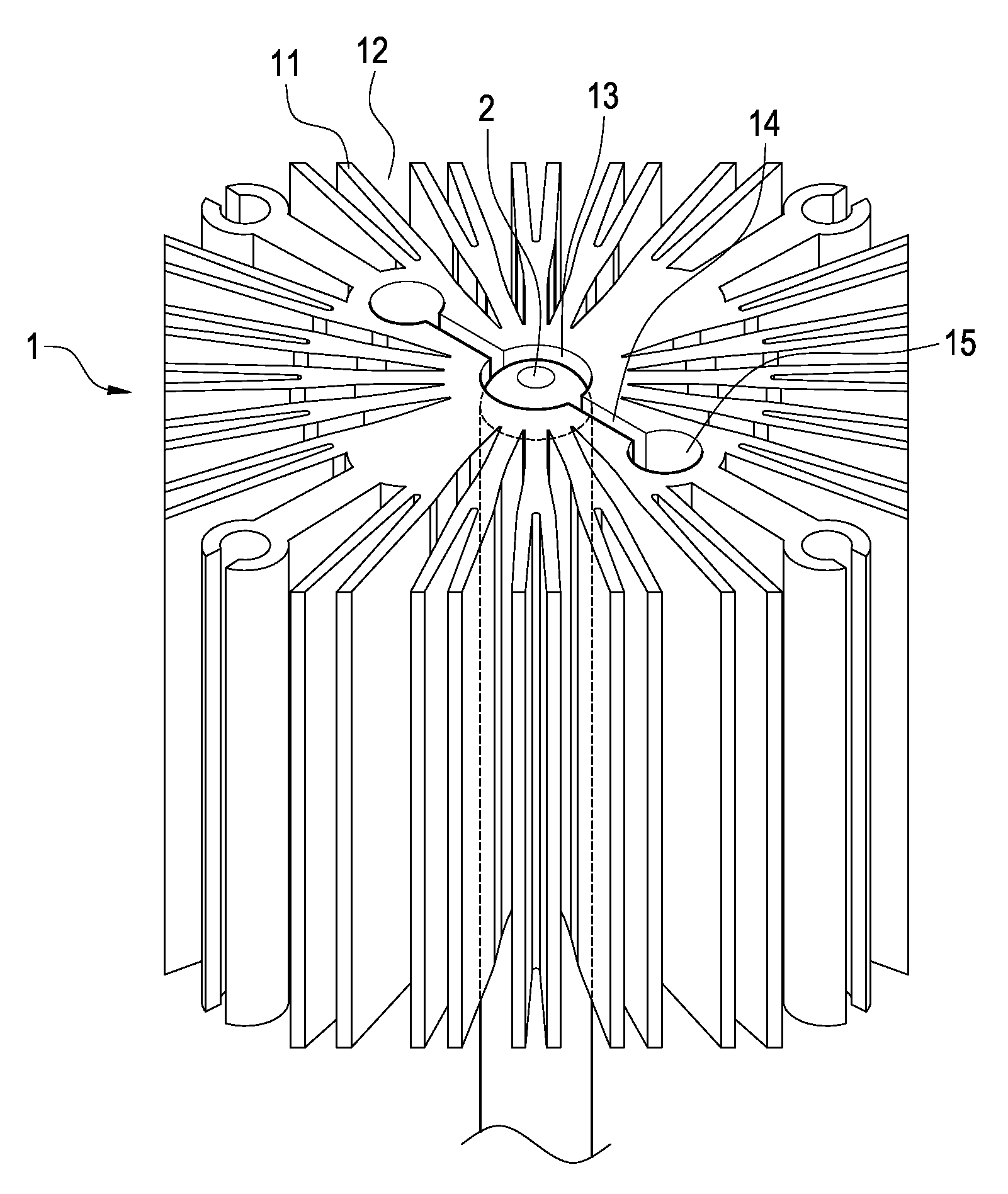
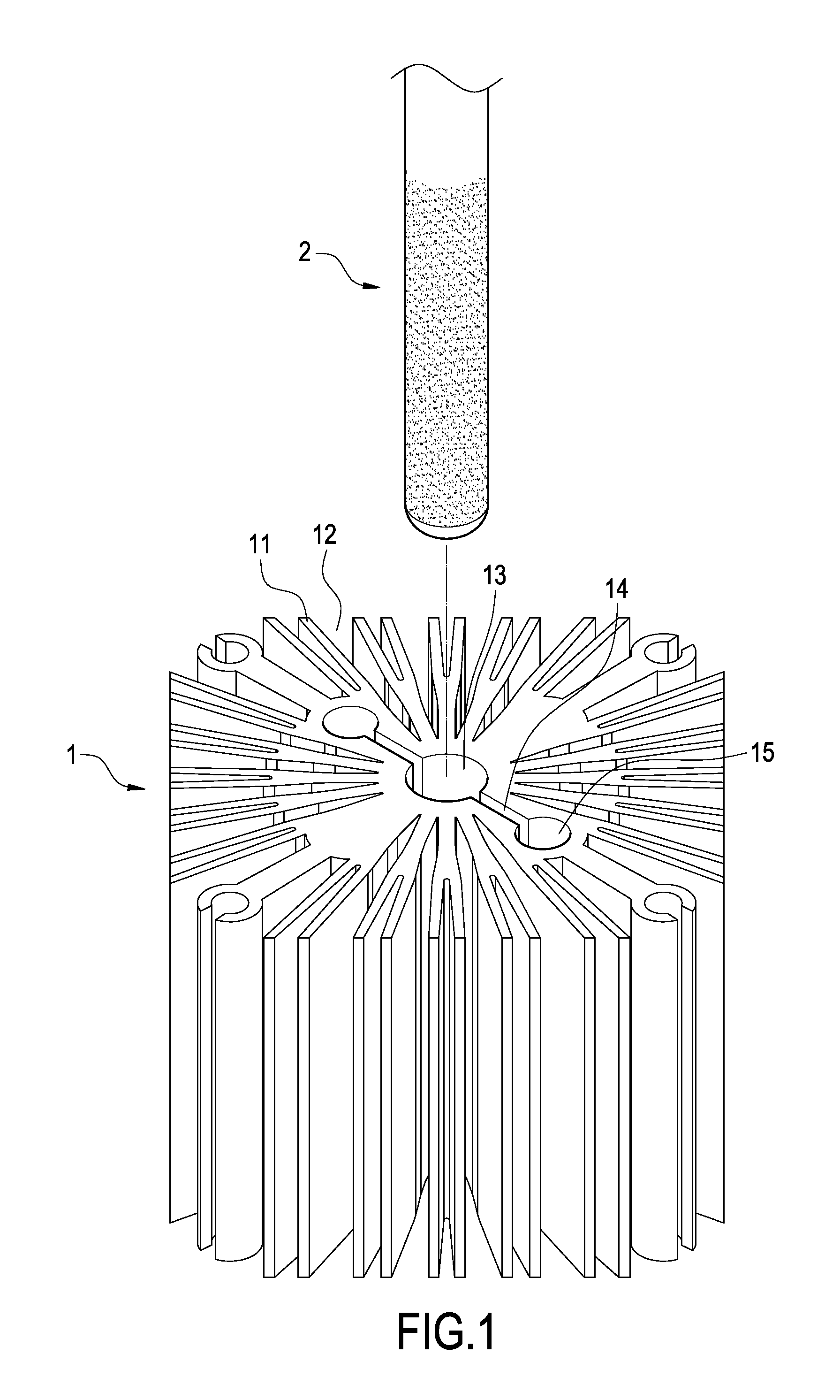
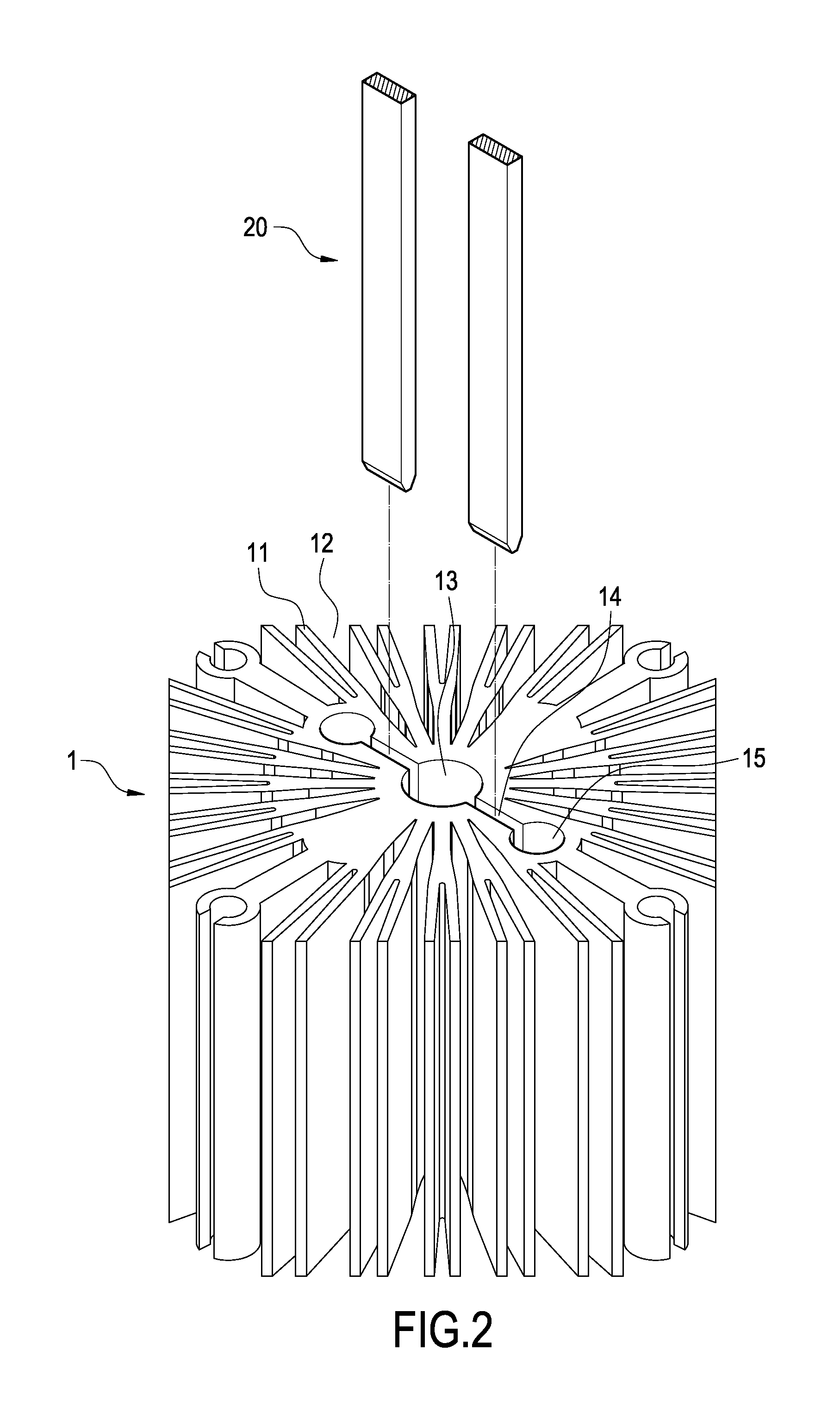
[0018]With reference to FIG. 1, it is a perspective view showing the structure of the present invention. As shown in the figure, the heat-dissipating structure of the present invention comprises a heat-dissipating body 1 and a heat pipe 2. The heat-dissipating body 1 has a plurality of radial heat-dissipating pieces 11. A gap 12 is formed between each heat-dissipating piece 11 to serve as a heat-dissipating path for the heat-dissipating pieces 11. Further, the central position of the heat-dissipating body 1 is provided with an accommodating trough 13. The cross section of the trough 13 is formed into a circular shape. The trough 13 penetrates through the heat-dissipating body 1 for accommodating the heat pipe 2. A plurality of corresponding slots 14 extends outwardly from the periphery of the trough 13. The plurality of slots 14 forms a straight...


PUM

PropertyMeasurementUnit
heat-aaaaaaaaaa
heat-dissipatingaaaaaaaaaa
structureaaaaaaaaaa

Abstract

A method for connecting a heat-dissipating body and a heat pipe and the structure thereof are used to improve the efficiency of heat conduction. The structure includes a heat-dissipating body and a heat pipe. The central position of the heat-dissipating body is provided with an accommodating trough for accommodating the heat pipe. A plurality of corresponding slots extends outwardly from the periphery of the trough. The other end of the slot is connected to a through hole. Tools are disposed in the slots to widen the slots and thus the periphery of the trough, so that the inner diameter of the trough is larger than the outer diameter of the heat pipe. After the heat pipe penetrates into the trough, the tools are removed, so that the inner wall surface of the trough abuts tightly against the outer circumferential surface of the heat pipe. Thus, the optimal efficiency of heat conduction between the heat pipe and the heat-dissipating body can be achieved.

Description

BACKGROUND OF THE INVENTION[0001]1. Field of the Invention[0002]The present invention relates to a heat-dissipating device, and in particular to a heat-dissipating structure having a heat pipe.[0003]2. Description of Prior Art[0004]With the progress of technology and modern materials, the current electronic products have more and more functions, and the volume thereof is gradually compacted. Since the electronic product is gradually compacted and exhibits high performance, the heat generated thereby is inevitably increased to a large extent. The heat generated by the electronic product will directly affect the operation and life thereof, and thus it is very important for the electronic industry to develop how to enhance the heat-dissipating effect.[0005]The heat-dissipating device having a heat pipe is one of the common heat-dissipating solutions. The structure thereof includes a heat pipe and a heat-dissipating body. The principle of heat dissipation is explained as follows. First,...

Claims


Application Information

Patent Timeline
Patent Type & Authority Applications(United States)
IPC IPC(8): F28D15/00H05K7/20
CPCF28D15/02F28F1/20F28F2275/10H01L23/427F28F2215/10Y10T29/49368H01L2924/0002Y10T29/49353Y10T29/53109H01L2924/00
Inventor LIN, KUO-LENHSU, KENCHENG, CHIH-HUNG
Owner CPUMATE INC
Why Eureka
Try Eureka