Supercharge Your Innovation With Domain-Expert AI Agents!

Positive lift vehicle

a positive lift and vehicle technology, applied in the direction of vertical landing/take-off aircraft, aircraft navigation control, transportation and packaging, etc., can solve the problems of insufficient development of the method to produce vehicles, the length of the air foil required is great, and the vehicle is difficult to operate safely in close quarters, so as to improve the lift and the overall vehicle mass.

Inactive Publication Date: 2008-05-29
VAZQUEZ JOSE E +1
View PDF6 Cites 0 Cited by
  • Summary
  • Abstract
  • Description
  • Claims
  • Application Information

AI Technical Summary

Benefits of technology

[0006]The invention comprises a vehicle having a platform, on which to support or carry persons or cargo, where the platform is encased in an enclosed body with a combined overall low center of gravity. An impeller is mounted for rotation at the top of the body powered by a motor located somewhere on the vehicle, preferably in the lower, central part, of the body. The impeller is designed to rotate at high speed to remove the air and the accompanying air pressure from the area about the impeller, thereby allowing the vehicle to be “lifted” into the air by the air pressure surrounding the lower part of the vehicle. In one embodiment, the impeller is magnetically attached to the drive system. In another embodiment, the body is hung below an envelope that is partially or fully filled with a buoyant gas, such as hydrogen or helium, to lessen the mass of the overall vehicle and improve the lift provided by the impeller.
[0007]It is preferred that the design of the vehicle allows for controlling the flow of air, displaced from the top of the vehicle, to cascade outward and downward over the vehicle's body to provide currents of air that may be deflected by vanes or other control surfaces mounted on the body, to direct the currents in order to change the direction of the vehicle's path over the ground.

Problems solved by technology

Unfortunately, the required length of these air foils is great, i.e., the wings and rotor are long, and the area on the ground required for safe operation of them (for takeoff and landing) is sufficiently large that they cannot operate safely in close quarters.
This method has not, to date, been significantly developed enough to produce operation of vehicles to transport humans and cargo above the ground.

Method used


Image

  • Positive lift vehicle
  • Positive lift vehicle
  • Positive lift vehicle

Examples


Embodiment Construction

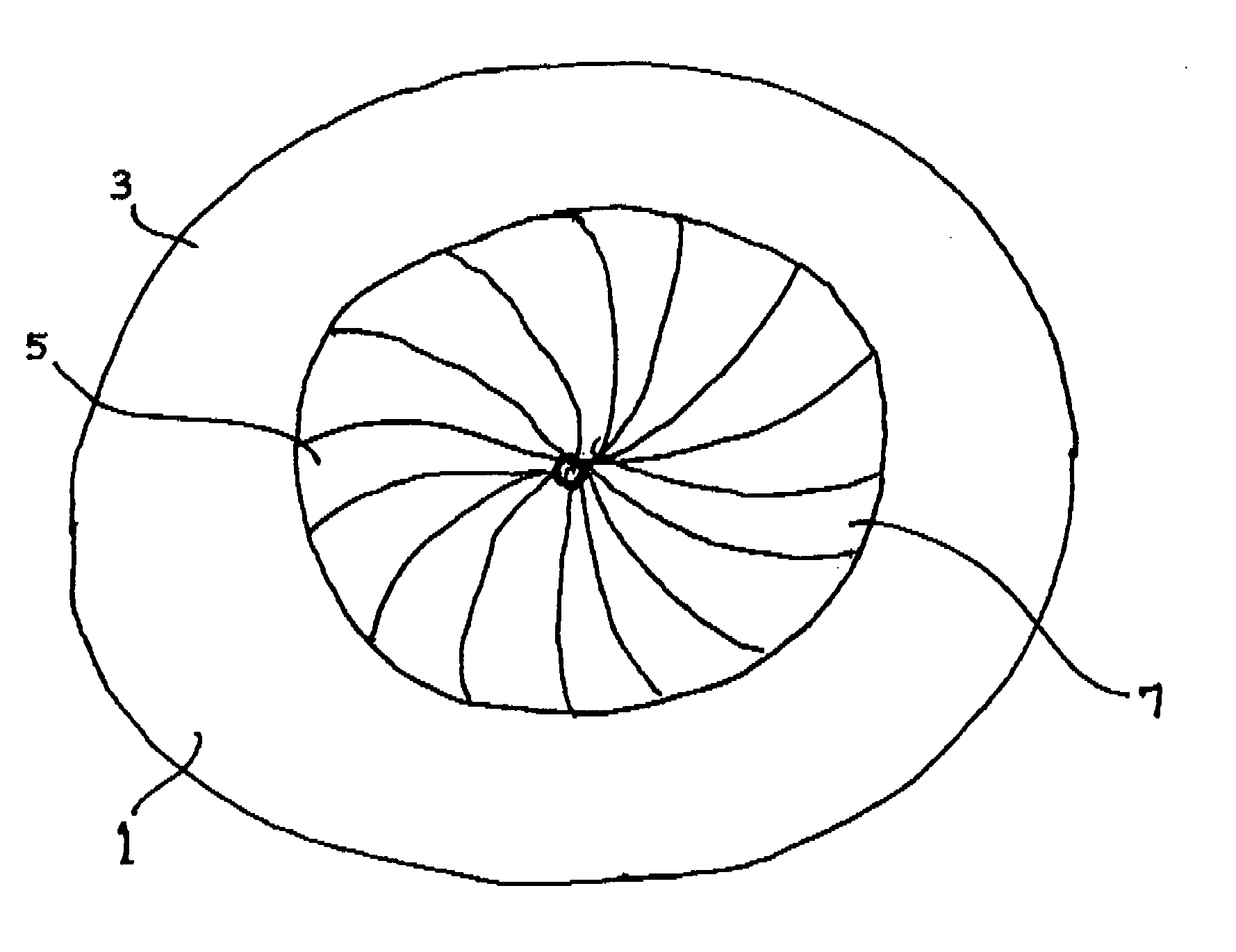
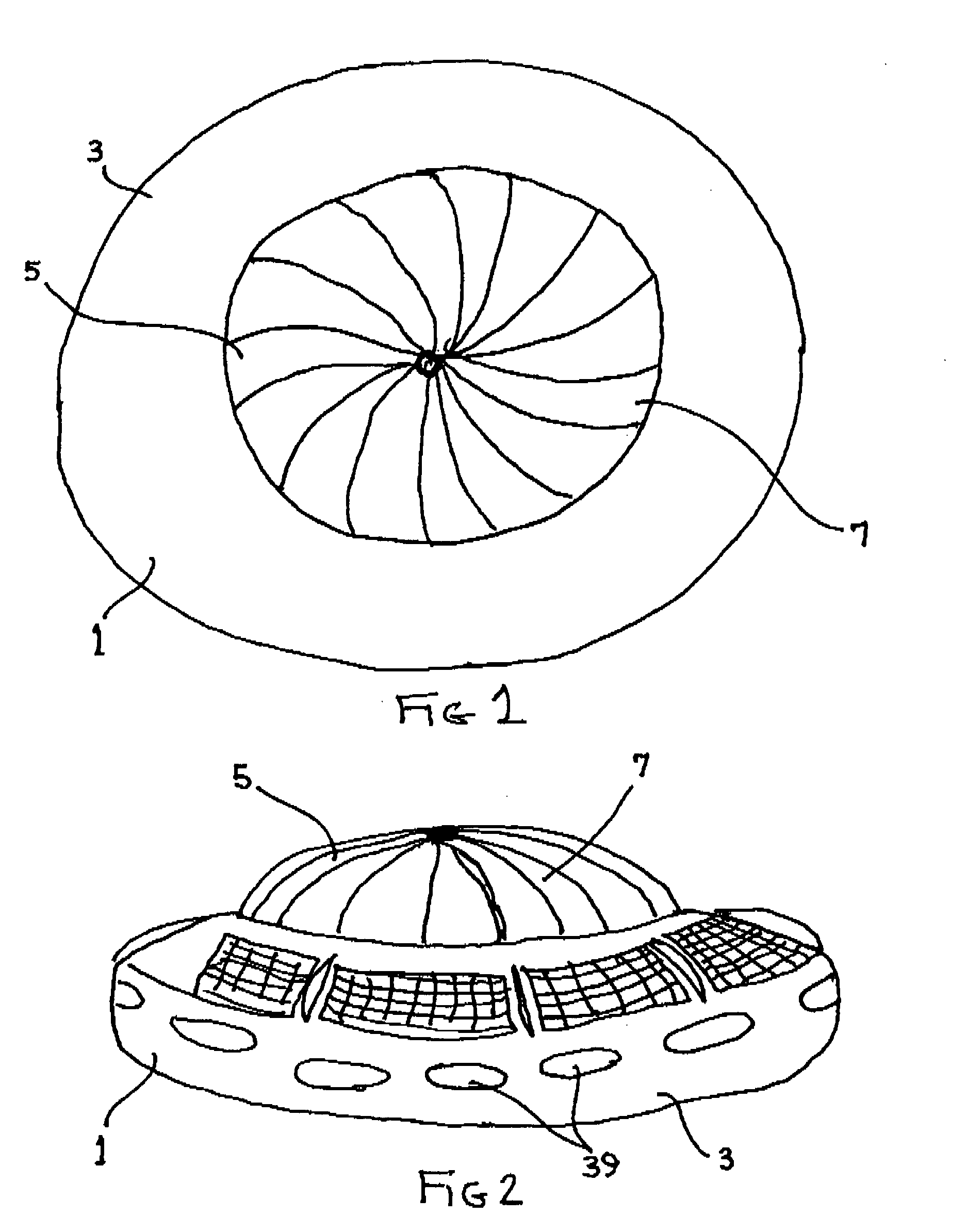
[0020]Turning now to the drawings, wherein like elements carry like numerals throughout the 12 Figures, the Figures show a vehicle 1 comprising a body 3, generally configured as an enclosed vessel, having a passenger and cargo platform interior thereof (not shown) and a top 5 centrally located above body 3. In general, while vehicle 1 remains unpowered, body 3 and top 5 are pressurized equally by the surrounding air. General air pressure at sea level is about 14.7 pounds per square inch gauge but may vary slightly depending upon local weather conditions. Suffice it to say, both body 3 and top 5 are stabilized in the surrounding air with the same pressure pressing down on the top of them as inward pressure about the sides and upward pressure from below body 3.

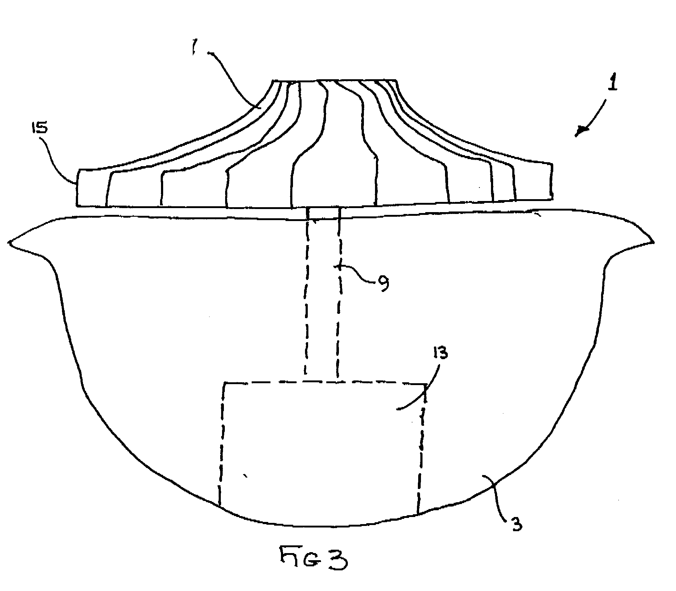
[0021]Top 5 contains an impeller 7 that is preferably mounted for rotation on a drive shaft 9, such as shown in FIG. 3, driven by a motor 13, preferably located centrally in the bottom or lower part of body 3 so as to give vehic...


PUM


Abstract

An air vehicle includes a body having a top and a bottom and a support platform for carrying cargo such a people or equipment. An impeller mounted on the body is powered, such as by a motor, for rotating so as to create low pressure on the top of the body relative to the pressure on the bottom of the body so as to create lift. The body may contain buoyant gas sufficient to aid in lift. Air from the impeller may be directed to directionally control the vehicle. A plurality of impellers may be used.

Description

CROSS-REFERENCE TO RELATED APPLICATIONS[0001]This application claims the benefit of U.S. Provisional Application No. 60 / 813,124, filed Jun. 13, 2006.FIELD OF THE INVENTION[0002]This invention relates to the field of heavier-than-air vehicles. More particularly, the invention relates to a means for rendering heavier-than-air vehicles capable of takeoff, maneuvering, and landing without the need for long runways, wide wings, and wide, rotating rotor blades.BACKGROUND OF THE INVENTION[0003]There are two general classes of vehicles capable of flying above the earth's surface; lighter-than-air vehicles, whose overall premise is that the weight of the vehicle is less than the weight of the air it displaces, thus “floating” in the air, and heavier-than-air vehicles that are heavier than the air they displace yet able to rise and fly by developing aerodynamic lift over some of the upper part of their body.[0004]In heavier-than-air vehicles, the “lift” is developed most popularly by applicat...

Claims


Application Information

Patent Timeline
IPC IPC(8): B64B1/20B64C27/22B64B1/34
CPCB64C39/064
Inventor VAZQUEZ, JOSE E.CALDERWOOD, ROBERT G.
Owner VAZQUEZ JOSE E
Features
  • R&D
  • Intellectual Property
  • Life Sciences
  • Materials
  • Tech Scout
  • Unparalleled Data Quality
  • Higher Quality Content
  • 60% Fewer Hallucinations
Learn More