Reinforced cover for gaps in an aerodynamic contour

a technology of aerodynamic contours and reinforced covers, which is applied in the direction of wings, wing adjustment, fuselages, etc., can solve the problems of unanticipated air flow behavior reducing aerodynamic efficiency, and possibly having a negative effect on aerodynamics

Active Publication Date: 2008-05-29
AIRBUS OPERATIONS SL
View PDF39 Cites 20 Cited by
  • Summary
  • Abstract
  • Description
  • Claims
  • Application Information

AI Technical Summary

Benefits of technology

[0016]The areas which require maximum reinforcement are usually the first section and the adjacent section, given that, on one hand, the first section corresponds to the attachment area, in other words, for attaching the cover to the fixed structural element of the vehicle, whilst the adjacent area which includes the aforementioned transition plane, is the area which includes the bending axis of the second section with regard to the first plane and, therefore, is subjected to continued bending stress. Therefore, the thickness of the fiberglass layer in the second section preferably decreases in direction towards the free end of the second section and, more preferably, the thickness of the fiberglass layer in the aforementioned adjacent area decreases progressively from the transition section towards the free end of the second section. In the other areas of the cover, the fiberglass layer is thinner, which makes it possible to reduce the total weight of the cover, which is especially important in aircraft.
[0018]The reinforcement which comprises the fiberglass layer of the cover of the present invention provides substantial advantages over the conventional reinforcements comprised of plastic or metal elements. Thus, first of all, with regard to the process of manufacturing the cover of the present invention, the different thicknesses required in the different areas of the cover and which allow to leave out reinforcement thicknesses in those areas which are not subjected to substantial stresses, are readily achieved by varying the thickness of the fiberglass layer, which contrasts with the need of achieving the different thicknesses by means of molding the plastic reinforcing elements and with the need of achieving the different thicknesses at the metal reinforcements for example by means of chemical milling.
[0019]In addition thereto, the use of fiberglass as a composite reinforcing material enhances, as compared to conventional reinforcements such as carbon fiber, galvanic compatibility of materials thus reducing the possibility of corrosion if mounted on aluminum components which are attacked by carbon fiber. On the other hand, also the galvanic incompatibility which the conventional metal reinforcement elements have against carbon elements which are part of many components of vehicles and particularly of aircraft, is avoided.
[0020]Another advantage of the fiberglass being used at the outside of the cover of the present invention is the fact that that outside can be painted, therefore increasing its resistance to weathering and noticeably improving the aesthetic finish of the cover, thus being susceptible of being an element which provides continuity to the paint pattern of the vehicle, whereby the requirements to the selected paint system (primer and finishing coating) are compatibility with fiberglass composite material, suitability to aerodynamic contour (high-solid finish) and a high degree of flexibility in order not to deteriorate with the flexions of the sealing.
[0022]In one embodiment of the cover of the present invention, the transition section extends along a slanted longitudinal axis which connects said first axial plane to said second axial plane. The slant of the outer surface of the transition section is not necessarily the same as that of the inner surface of said section. Thus, the slant of the outer surface may be the same as that of a beveled edge of the outer surface of the fixed part of the vehicle, whilst the interior slant may be slanted to a greater degree for the purpose of increasing the thickened area of the main body.
[0026]According to one embodiment of the cover of the present invention especially useful for aircraft and, particularly for covering the gaps at the elevators and rudders and at the flaps of the type described hereinabove, the first section which forms the attachment tab is stage-shaped for bolting it to a structural element such as a metal or carbon fiber panel, with a bevel on its inner surface for housing the stage. The rigidity of this tab, achieved with greater thicknesses of the fiberglass layer, allows for it to be easily mechanized, such that interferences are avoided and the integration thereof into the structure is facilitated. Likewise it allows the attachment elements, such as rivetable nuts, to be mounted thereat, so that no additional metal profile as is usually used for preventing rips in the cloth-reinforced seals, is needed for reinforcing the attachment. This alternative is suitable in cases where it is desired to remove the seal without the need of accessing the inside of the structure, as the seal itself retains the nut without any need of using a spanner, which would be necessary for conducting inspections of the assembly of fittings supporting the moving aerodynamic surface. The tab can also take an attachment made directly using conventional bolt, nut and washer.

Problems solved by technology

This problem is especially important for aircraft.
As the internal (non-aerodynamic) elements are exposed the air current may become deflected, this giving rise to the aforementioned unanticipated behaviors in the air flow.
In addition thereto, when there are gaps of this type in two parts of the structure separated from each other which are connected to each other, a flow of air is generated in the interior of the structure which, at the outlet opening, may cause flow separations, thus reducing the aerodynamic efficiency, it therefore being necessary for the sealing of such gaps to cover the largest part possible thereof in order to create an effective barrier which will restrain or even block this flow of air.
Although these seals are capable of withstanding major deflections, their lack of reinforcement may lead, under certain conditions, such as, for example, at high cruising speeds, to a flapping of the tongue being caused, thus reducing its efficiency and possibly having a negative effect on the aerodynamics.
In addition thereto, in the movements in which the friction against the moving surface tends to contract the seal, blockages may occur, especially if there are grime build-ups.
A second type of seal is a tongue-shaped seal with internal cloth reinforcement, covered with low-friction polyester fabric, which, although it improves the negative aspects of the non-reinforced tongue-shaped seals, entails the drawback of the reinforcement provided by the cloth not being sufficient to reduce the aforementioned flapping to the desired levels.
A third type of seal is a tongue-shaped seal with integrated plastic or metal reinforcement, covered by low-friction fabric, which, although having a suitable rigidity, needs an auxiliary structure for supporting the seal, as a result of which, although positively solving the aerodynamic problems, it is of an unacceptable structural weight.

Method used


Image

  • Reinforced cover for gaps in an aerodynamic contour
  • Reinforced cover for gaps in an aerodynamic contour
  • Reinforced cover for gaps in an aerodynamic contour

Examples


Embodiment Construction

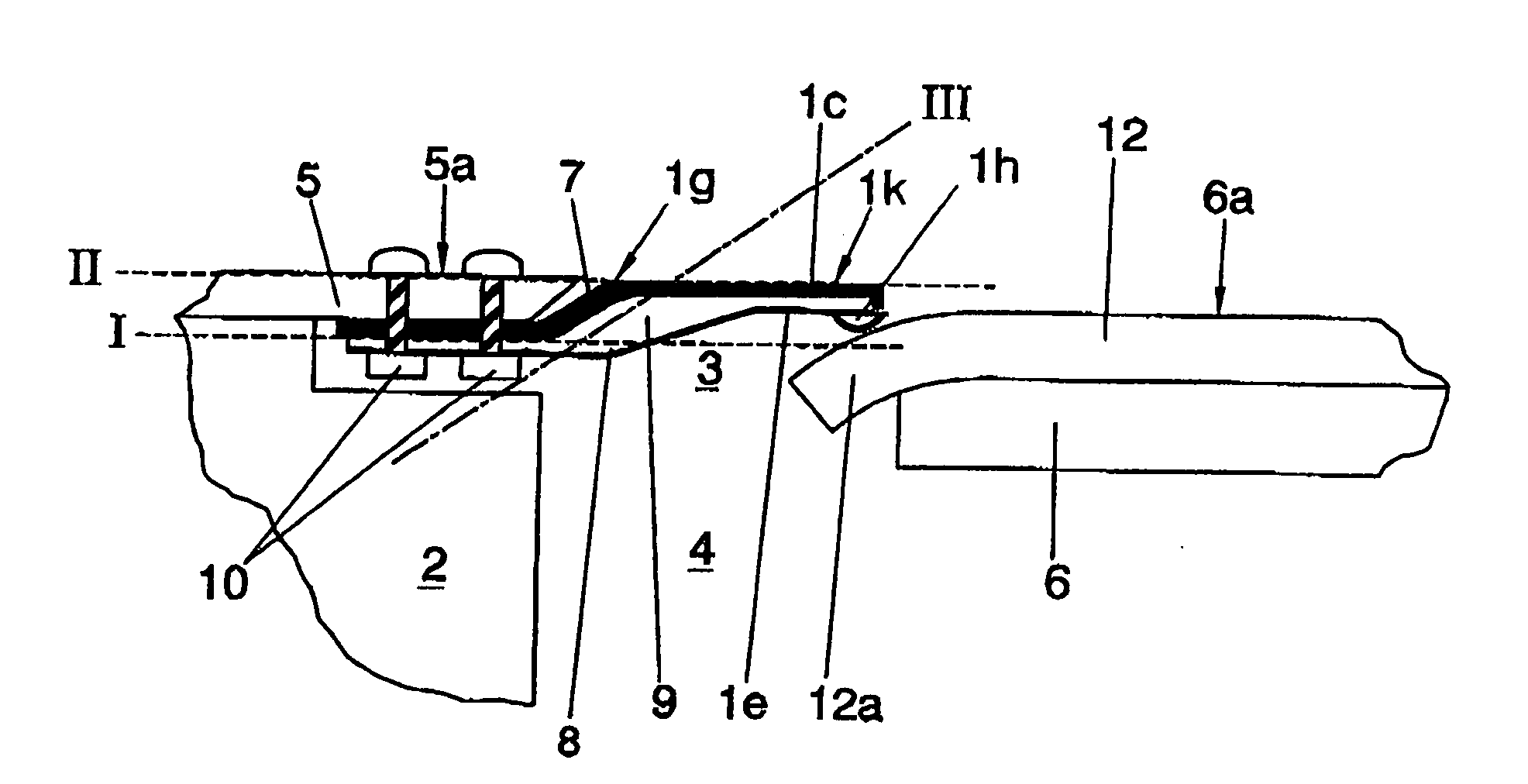
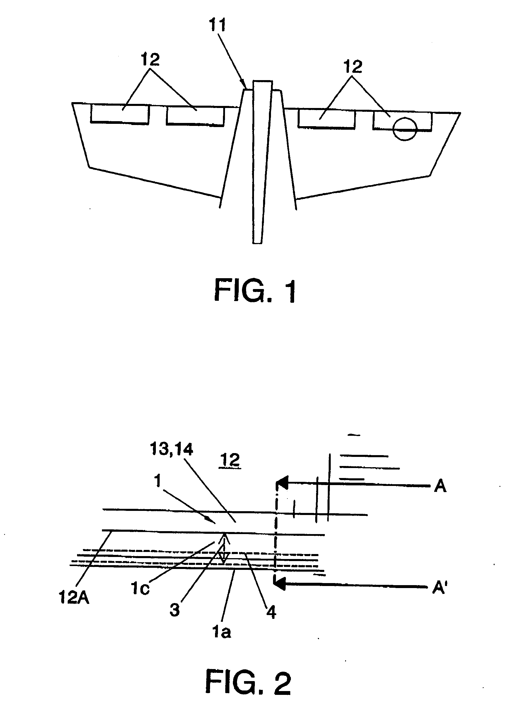
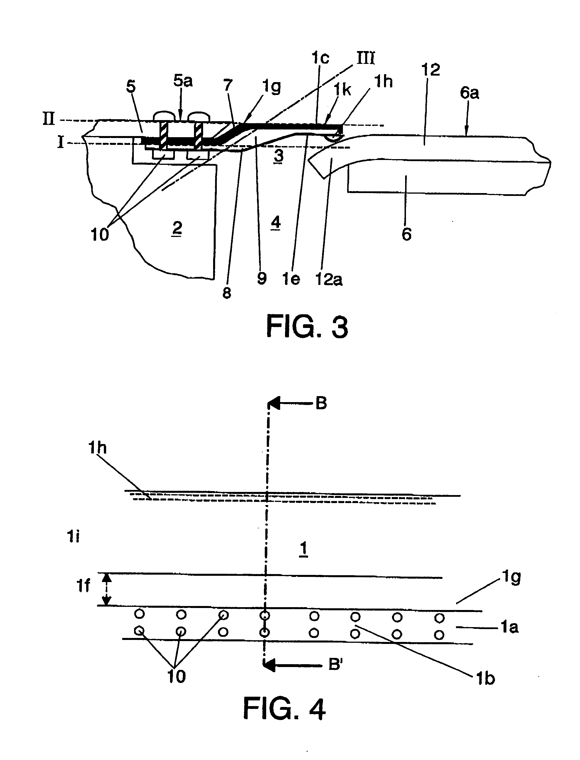
[0011]It is an object of the present invention to overcome the drawbacks of prior art stated hereinabove by means of a reinforced cover for gaps in the aerodynamic contour of a vehicle, particularly for an aircraft, which comprises a first attachment section attachable to a structural element of the vehicle by attachment means, a second elastic tongue-shaped section with an extension which covers at least partially an existing gap between two parts of the outer surface of a vehicle, such as, for example, a fixed part and a moving part of the vehicle, and with a free end which ends on the outer surface of the moving part, reinforcement means, and a layer of low sliding friction, such as, for example, a layer of polyester fabric, which covers at least partially the inner surface of the second section, a main internal body of an elastic material, such as, for example, silicone rubber, in which cover

[0012]the reinforcement means comprises at least one fiberglass layer formed at the oute...


PUM


Abstract

Reinforced cover for gaps in an aerodynamic contour of a vehicle, with a first attachment section 1a attachable to a structural element 2, 5 of the vehicle 11, on a first axial plane I; a second elastic section 1c which covers a gap 3 which is located between a fixed part 5 and a moving part 6, 12 of the vehicle 11, and provided with a low-friction coating 8 on its inner surface 1e, an outer surface 1k with a fiberglass layer 7a; a main internal body 9 of an elastic material, a flexible transition section 1g between the first and the second section, 1a, 1c; the outer surface 1k of the second section 1c flushing with the outer surface 5a and extending towards the free end 1d as a continuation of the outer surface 5a of the fixed part 5.

Description

RELATED APPLICATION[0001]The present application claims priority from Spanish Application Serial No. 200403163, filed on Dec. 31, 2004. Applicants claim priority under 35 U.S.C. §119 as to said Spanish application, the entire disclosure of which is incorporated herein by reference in its entirety.TECHNICAL FIELD OF THE INVENTION[0002]The present invention pertains to the field of the covers used for covering gaps which have an effect on the aerodynamic properties of outer surfaces of vehicles such as aircraft and high-speed trains. This invention is particularly encompassed within the sector of the covers used for covering gaps located between the surface of a moving element and the surface of a fixed element of such a vehicle.PRIOR ART TO THE INVENTION[0003]On high-speed vehicles such as aircraft and high-speed trains, there are moving elements, such as may be, for example, on aircraft, the elevators and rudders or flaps, which are articulated to fixed elements, between which there...

Claims


Application Information

Patent Timeline
Patent Type & Authority Applications(United States)
IPC IPC(8): B64C1/38
CPCB64C7/00B64C9/00
Inventor HERNANDEZ, AGUSTIN MARIANO MARTIN
Owner AIRBUS OPERATIONS SL
Why Eureka
Try Eureka