Heat spreader for an electrical device

Inactive Publication Date: 2008-05-29
WANG CHUNG CHENG
View PDF6 Cites 50 Cited by
  • Summary
  • Abstract
  • Description
  • Claims
  • Application Information

AI Technical Summary

Benefits of technology

[0010]It is therefore an object of the invention to solve the mentioned-above problems, according to the heat spreader of the present invention, said heat spreader which is above and corresponding to a chip coupled with a base of an electrical device includes a first portion, a second portion, a connecting portion, a supporting portion and a side edge, said connecting portion is between said first portion and said second portion, said heat spreader is predetermined shape; according to the heat spreader of the present invention, (i). Due to the side edge of said heat spreader can be protruded and exposed to the side wall of encapsulant (refer to the detailed descriptions in FIG.3), in this manner, a larger chip enables to be accommodated in said heat spreader, furthermore, due to a portion of said heat spreader enables to be exposed to the side wall of encapsulant, in this manner, a new (added) path for heat dissipation of chip being formed, then the heat dissipation for a chip is enhanced, and then the reliability of the chip enables to be enhanced. Accordingly, it is more useful and more reliable for the heat spreader in accordance with the

Problems solved by technology

Nowadays, electrical devices are becoming more powerful than before, and usually, the more powerful the electrical device is, the hotter the electrical device is, due to a high-density chip is involved in the electrical device, the chip will generate heat while operating, nevertheless, it is not good for a chip to keep working in such a heating environment, due

Method used


Image

  • Heat spreader for an electrical device
  • Heat spreader for an electrical device
  • Heat spreader for an electrical device

Examples


Embodiment Construction

[0025]Embodiments of heat spreader in accordance with the present invention will be explained with reference to the drawings as follow:

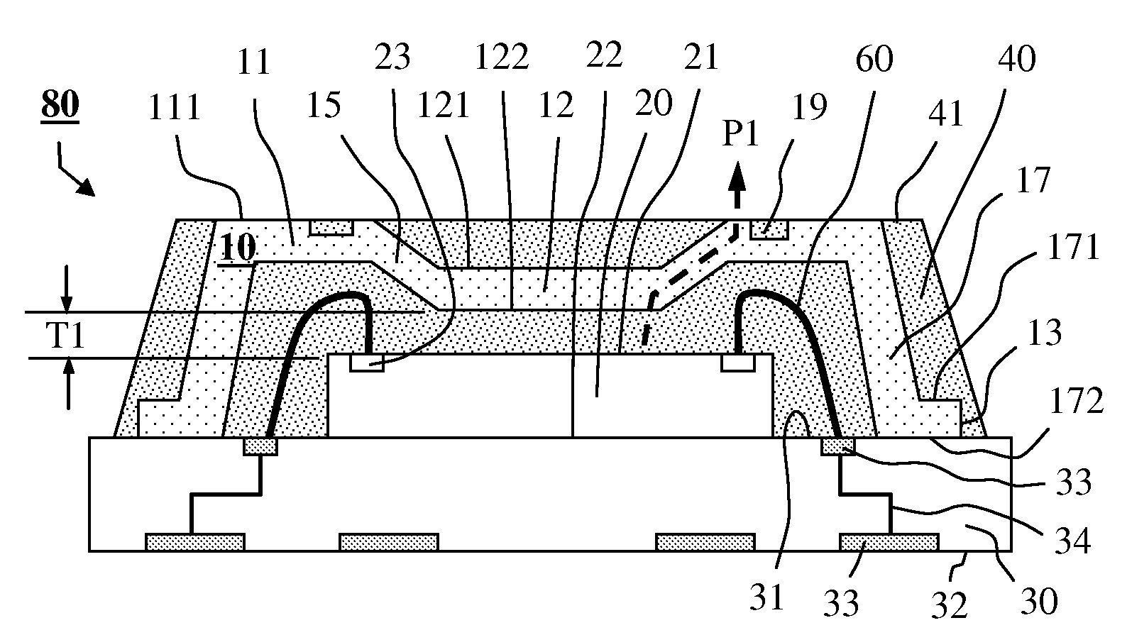
[0026]FIG. 1 is a cross sectional view of a preferred embodiment of the heat spreader 10 in accordance with the present invention, said heat spreader 10 consists of the primary characteristics related to the heat spreader in accordance with the present invention, said heat spreader 10 is comprising: a first portion 11 having an upper surface 111 and a corresponding lower surface 112, a second portion 12 having an upper surface 121 and a corresponding lower surface 122 and a connecting portion 15 having an upper surface 151 and a corresponding lower surface 152, said connecting portion 15 is between said first portion 11 and said second portion 12 of heat spreader 10, wherein the first portion 11 and the second portion 12 are not in the same horizontal level, and the heat spreader 10 formed by the first portion 11, second portion 12 and connecting por...


PUM


Abstract

A heat spreader for electrical device is disclosed, a portion of said heat spreader is above and corresponding to a chip which is coupled with a base of electrical device. An embodiment for the heat spreader comprised of: a first portion, second portion, connecting portion, supporting portion and a side edge, said connecting portion is between said first portion and said second portion, said supporting portion coupled with the base of electrical device, said supporting portion is connected to the periphery of said first portion in order that said chip can be accommodated in said heat spreader; according to the heat spreader of the present invention, (i). Due to the side edge of said heat spreader can be protruded and exposed to the side wall of encapsulant, in this manner. Not only a larger chip can be placed in the heat spreader but the heat dissipation for said chip becomes more effective. (ii). More surfaces of said heat spreader enables to be encapsulated by an encapsulant, in this manner, the reliability of electrical device enables to be enhanced

Description

BACKGROUND OF THE INVENTION[0001]1. Field of the Invention[0002]The present invention relates to a heat spreader which is involved in an electrical device, more particularly, it relates that a heat spreader enables to be dissipating the heat of electrical device for enhancing the reliability of electrical device more effectively and be accommodating a larger chip therein for being more useful in the electronic industry.[0003]2. Description of the Related Art[0004]Nowadays, electrical devices are becoming more powerful than before, and usually, the more powerful the electrical device is, the hotter the electrical device is, due to a high-density chip is involved in the electrical device, the chip will generate heat while operating, nevertheless, it is not good for a chip to keep working in such a heating environment, due to it is easy to cause the chip to be not functional well, once the chip is not functional well, then the electrical device does not work well either, in this manner...

Claims


Application Information

Patent Timeline
IPC IPC(8): H01L23/34
CPCH01L2224/48227H01L2224/16245H01L2224/97H01L2225/0651H01L2225/06589H01L2924/01013H01L2924/01029H01L2924/01078H01L2924/01079H01L2924/01082H01L2924/15174H01L2924/15184H01L2924/16152H01L2224/48235H01L2224/16225H01L2924/12041H01L2924/01074H01L2924/01033H01L2924/01019H01L23/4334H01L24/97H01L25/0657H01L2224/48091H01L24/48H01L2924/01006H01L2924/00014H01L2224/85H01L2224/81H01L2924/351H01L2224/0557H01L2224/05573H01L2924/181H01L2924/18165H01L2224/05571H01L2224/0554H01L2924/00H01L2224/05599H01L2924/00012H01L2224/45099H01L2224/45015H01L2924/207H01L2224/0555H01L2224/0556
Inventor WANG, CHUNG-CHENG
Owner WANG CHUNG CHENG
Why Eureka
Try Eureka