Plasma display device

Inactive Publication Date: 2008-05-29
LG ELECTRONICS INC
View PDF13 Cites 1 Cited by
  • Summary
  • Abstract
  • Description
  • Claims
  • Application Information

AI Technical Summary

Benefits of technology

[0007]The present invention provides a plasma display device in which auxiliary electrodes are disposed in parallel with sustain electrodes and overlap respective corresponding horizont

Problems solved by technology

This PDP architecture, however, results

Method used


Image

  • Plasma display device
  • Plasma display device
  • Plasma display device

Examples


Embodiment Construction

[0039]The present invention will hereinafter be described in detail with reference to the accompanying drawings in which exemplary embodiments of the invention are shown.

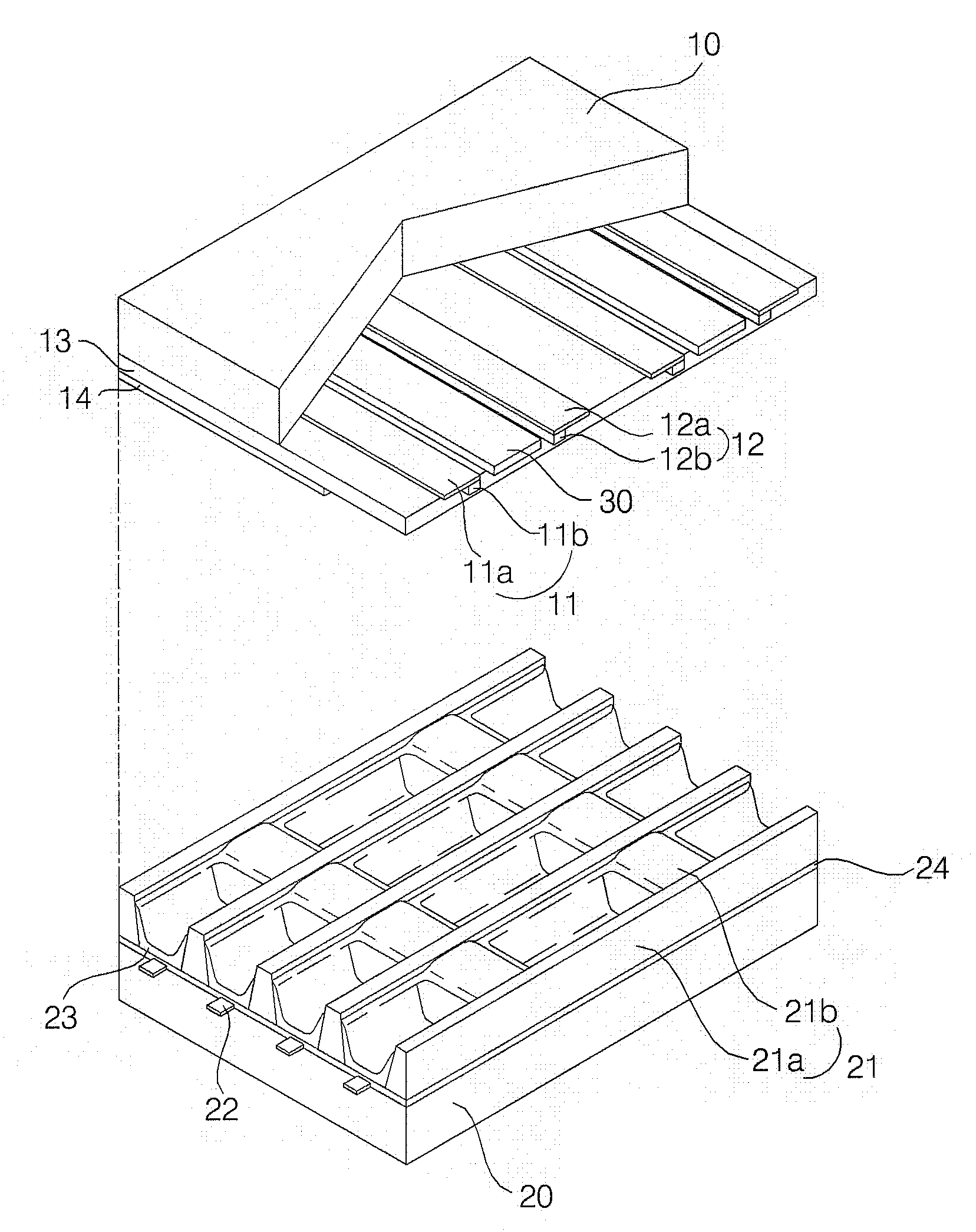
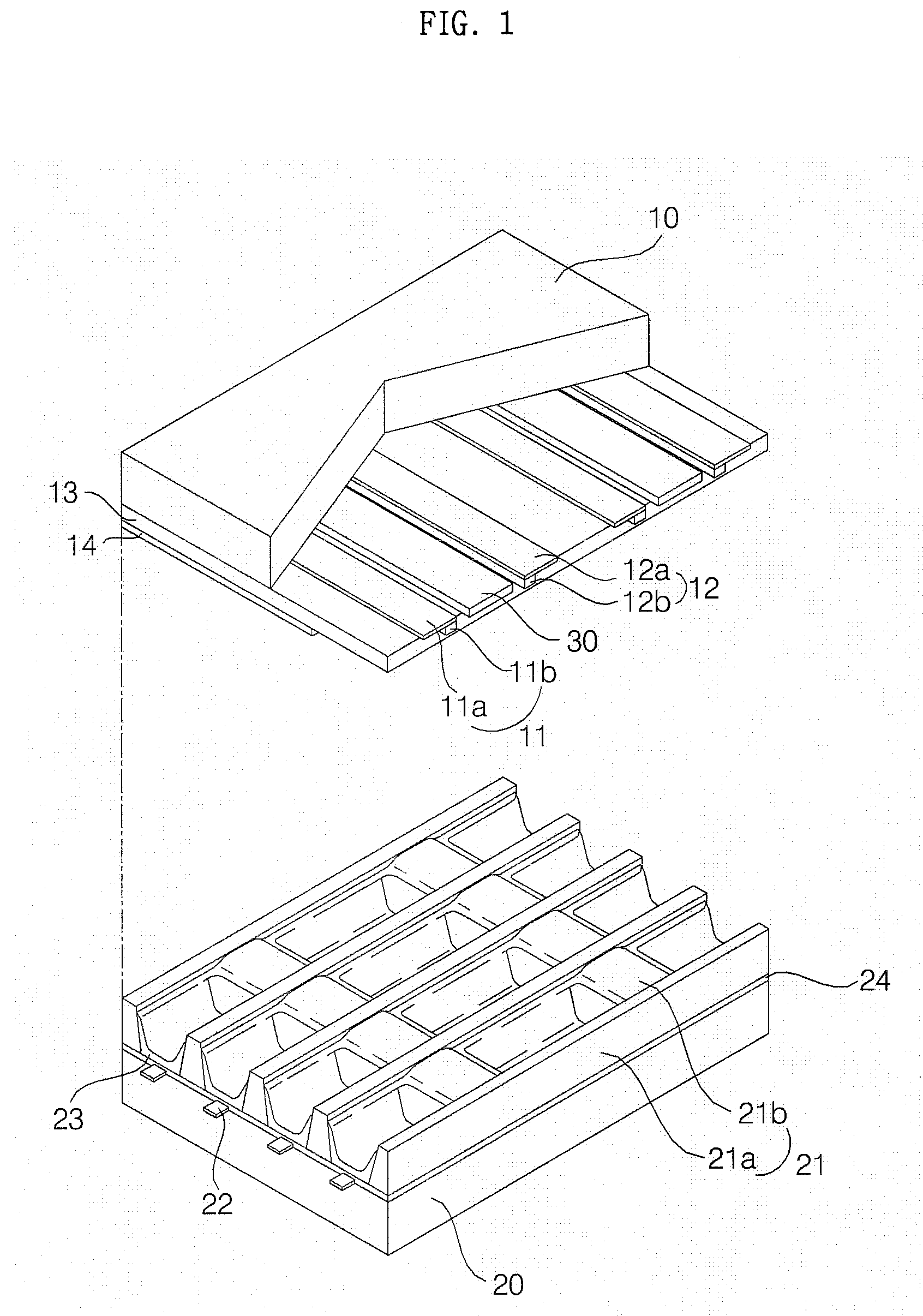
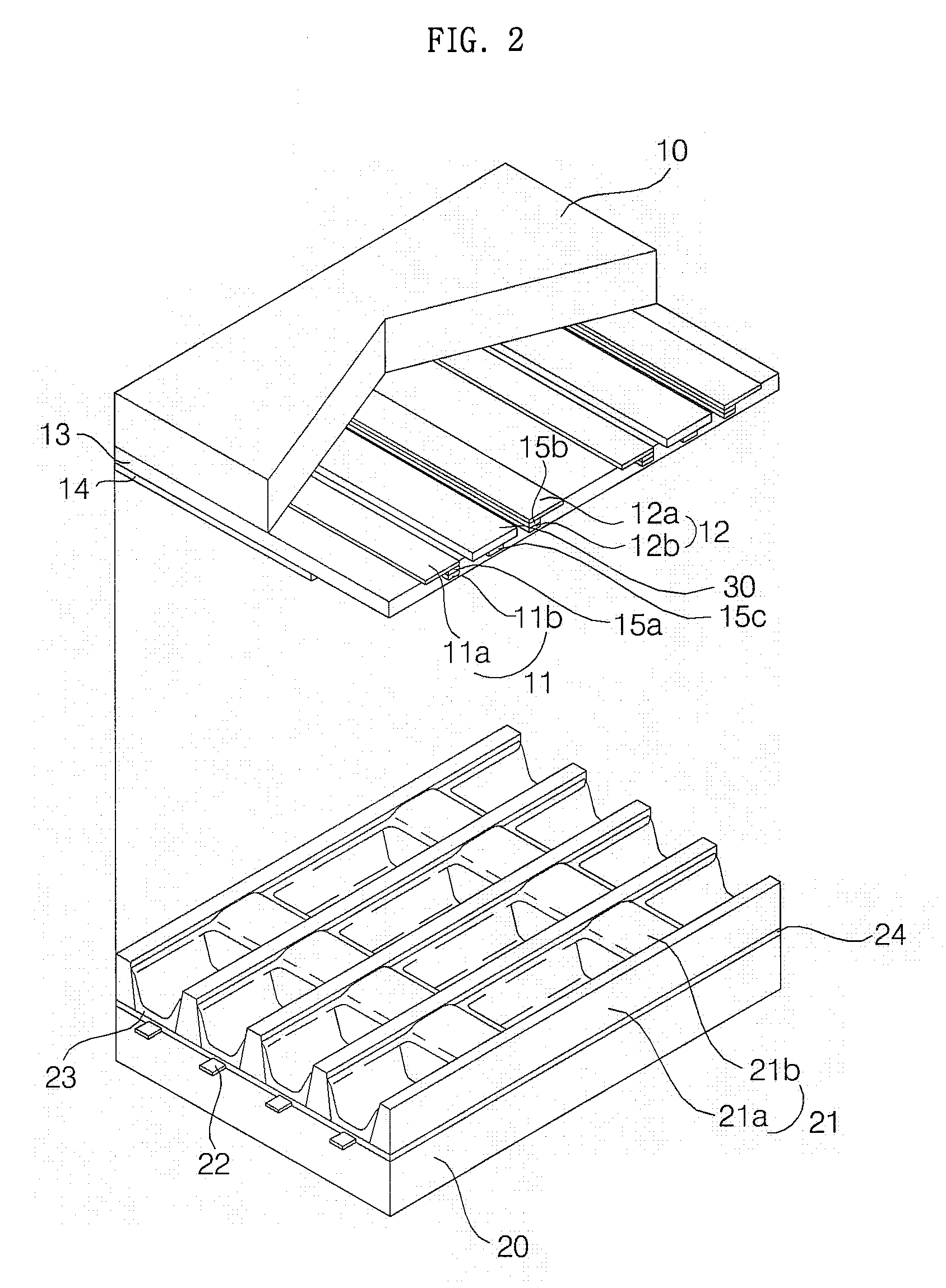
[0040]FIG. 1 is a perspective view of a plasma display panel (PDP). Referring to FIG. 1, the PDP includes an upper substrate 10, a plurality of sustain electrode pairs which are formed on the upper substrate 10 and consist of a scan electrode 11 and a sustain electrode 12 each; a lower substrate 20; and a plurality of address electrodes 22 which are formed on the lower substrate 20.

[0041]Each of the sustain electrode pairs includes transparent electrodes 11a and 12a and bus electrodes 11b and 12b. The transparent electrodes 11a and 12a may be formed of indium-tin-oxide (ITO). The bus electrodes 11b and 12b may be formed of a metal such as silver (Ag) or chromium (Cr) or may be comprised of a stack of chromium / copper / chromium (Cr / Cu / Cr) or a stack of chromium / aluminium / chromium (Cr / Al / Cr). The bus electrodes 11b and ...


PUM


Abstract

A plasma display device is provided. The plasma display device includes a plasma display panel (PDP); an upper substrate and a lower substrate which face each other; a plurality of scan electrodes and a plurality of sustain electrodes which are disposed on the upper substrate; a plurality of first barrier ribs which are disposed on the lower substrate in parallel with the scan electrodes and the sustain electrodes; a plurality of second barrier ribs which are disposed on the lower substrate, intersect the first barrier ribs, and are higher than the first barrier ribs; and a plurality of auxiliary electrodes which are disposed on the upper substrate and overlap the first barrier ribs. Accordingly, it is possible to improve the luminance and brightness of a PDP by forming horizontal barrier ribs to be lower than vertical barrier ribs. In addition, it is possible to reduce the amount of invalid power of a PDP by preventing crosstalk from occurring between a pair of sustain electrodes with a barrier rib interposed therebetween.

Description

[0001]This application claims priority from Korean Patent Application No. 10-2006-0117110 filed on Nov. 24, 2006 in the Korean Intellectual Property Office, the disclosure of which is incorporated herein by reference in its entirety.BACKGROUND OF THE INVENTION[0002]1. Field of the Invention[0003]The present invention relates to a plasma display device, and more particularly, to a plasma display device in which the amount of invalid power generated during the operation of a plasma display panel (PDP) can be reduced by forming auxiliary electrodes on an upper substrate so that the auxiliary electrodes can overlap respective corresponding horizontal barrier ribs.[0004]2. Description of the Related Art[0005]Plasma display panels (PDPs) are display devices which display an image, including text data and graphic data, by applying a predetermined voltage to a number of electrodes installed in a discharge space to cause a gas discharge and then exciting phosphors with the aid of plasma that...

Claims


Application Information

Patent Timeline
IPC IPC(8): H01J17/49
CPCH01J11/12H01J11/28H01J11/30H01J2211/365H01J11/36H01J2211/326H01J2211/363H01J11/32H01J11/22
Inventor AHN, SUNG YONG
Owner LG ELECTRONICS INC
Why Eureka
Try Eureka