
Luminance control for a display

a technology for controlling the brightness of the display and the backlight is applied in the field of display arrangement, which can solve the problems of power consumption, poor contrast, and the backlight used to illuminate the lcd in such products is usually consuming much more power than the lcd itself, and achieves the effect of reducing the power consumption, simple, flexible and accura

Inactive Publication Date: 2008-05-29
SONY ERICSSON MOBILE COMM AB
View PDF3 Cites 51 Cited by
  • Summary
  • Abstract
  • Description
  • Claims
  • Application Information

AI Technical Summary

Benefits of technology

[0012]The present invention is directed to providing a user of a portable imaging device with a simple, flexible, and accurate detection of the light conditions external to a portable device so as to enable a reduction of the power consumed by the illumination device of a display in the portable device, and so as to enable an adjustment of the illumination of the display to correspond to the inherent adaptation of the human eye to light levels. In particular, implementations of the present invention use existing components in portable imaging devices to achieve such illumination control.
[0013]One implementation of the present invention thus provides a user of a portable imaging device with a simple, flexible, and accurate detection of the light conditions surrounding a portable device so as to enable a reduction of the power consumed by the illumination device of a display in the portable device, and / or so as to enable an adjustment of illumination levels of the display based on the inherent adaptation of the human eye.

Problems solved by technology

The backlight used to illuminate the LCD in such products is usually consuming much more power than the LCD itself.
Because the reflected light is also attenuated twice in the translucent parts of the display image, however, contrast is usually poorer than in a transmissive display.
However, the absence of an internal illumination device significantly reduces the power consumption, allowing for longer battery life in battery-powered devices; small reflective LCDs typically consume so little power that they can rely on a photovoltaic cell, as is often found in digital watches, pocket calculators, etc.
Moreover, the illumination device (backlight) used in more demanding applications to illuminate an LCD and similar displays consumes much more power than the display device itself.
The extra mechanism increases the component costs of the portable device.
Moreover, the extra sensor requires additional space and an additional opening in the portable device, which increases the manufacturing costs and the overall size and complexity of the functional design of the portable device.

Method used


Image

  • Luminance control for a display
  • Luminance control for a display
  • Luminance control for a display

Examples


Embodiment Construction

[0049]The present invention relates to portable devices having an imaging system, such as a camera arrangement. In particular, the invention relates to a communication device including an imaging system. It should be appreciated that the invention is not limited to communication devices. Rather, implementations of the invention can be applied to any suitable portable device that includes a suitable imaging system.

[0050]The terms “image” or “images” are intended to comprise still images, a series or sequence of images, as well as moving images, unless otherwise is explicitly stated or is clear from the context.

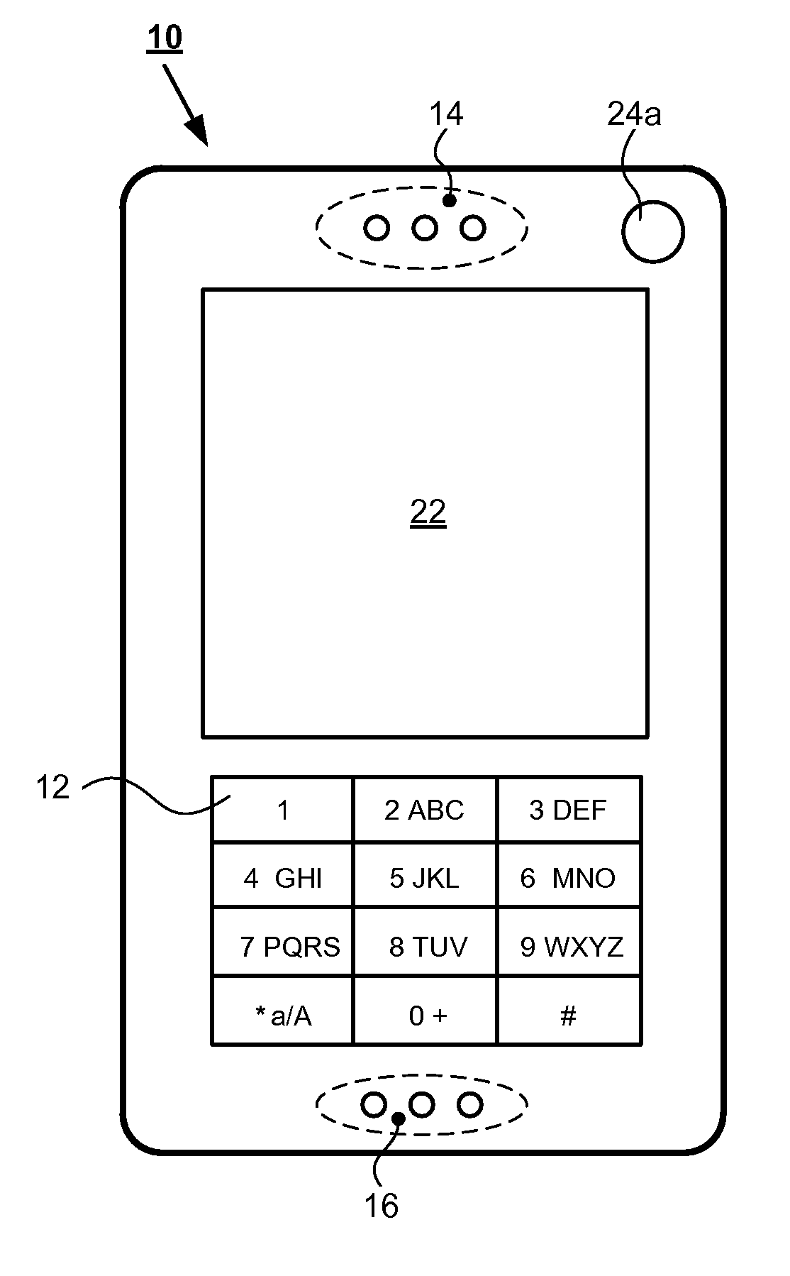
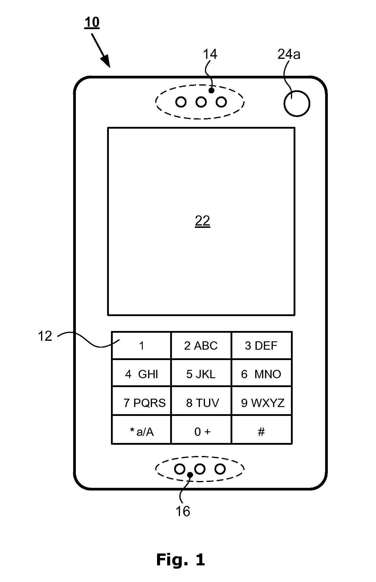
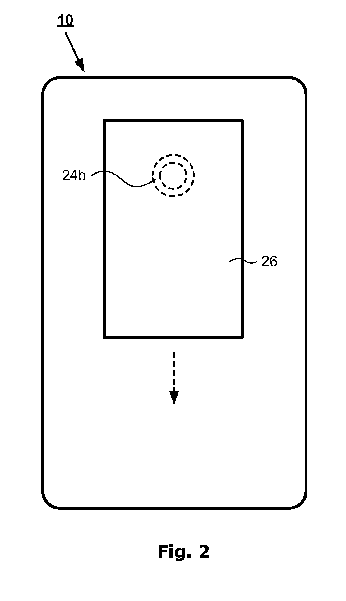
[0051]A portable communication device according to one embodiment of the present invention is shown in FIGS. 1 and 2. The device may include a phone 10, such as a mobile cell phone, adapted to operate according to 3G-technology (e.g., W-CDMA or CDMA2000) or possibly according to 2,5-technology (e.g., GPRS) or other communication technology. Information about 3G-technology and 2...


PUM


Abstract

A portable device may include at least one image recording device having a first light sensitive unit configured to record an image and detect first light conditions related to the portable device; a display to render the recorded image; and an illumination device to illuminate the display, wherein the illumination device is configured to control an illumination of the display based on the detected first light conditions.

Description

RELATED APPLICATIONS[0001]This application claims priority under 35 U.S.C. § 119 based on U.S. Provisional Application Ser. No. 60 / 867,154, filed Nov. 24, 2006, the disclosure of which is incorporated herein by reference.TECHNICAL FIELD OF THE INVENTION[0002]The present invention relates to portable devices including an imaging system and, more particularly, to a method and an arrangement for controlling a display in an imaging system of a portable device.BACKGROUND OF THE INVENTION[0003]Portable imaging devices are often provided with at least one camera for recording images captured by a user of the device. Recently, imaging devices have been digitalized, and traditional light sensitive silver-based film has been replaced by an electronic light sensitive receiver, e.g., such as a charge-coupled device (CCD) or similar device. In current portable devices, it has become increasingly common to use CMOS image sensors, such as. active pixel sensors (APS). In contrast to CCDs° CMOS imag...

Claims


Application Information

Patent Timeline
Patent Type & Authority Applications(United States)
IPC IPC(8): G09G5/00
CPCG03B17/20G09G3/3406G09G2360/144H04M1/22H04W52/027H04N1/00307H04N1/00835H04N1/00912H04M2250/52G01J1/0233G01J1/32G01J1/4204G01J1/4228Y02D30/70
Inventor NILSSON, RENEEK, MARTIN
Owner SONY ERICSSON MOBILE COMM AB
Learn More