Digital transmission system and clock reproducing device

a transmission system and clock technology, applied in the field of digital transmission systems, can solve the problems of complicated transmission system configuration, inability to change the vco oscillation frequency range immediately on the receiving side, and complicated configuration of the transmission system

Inactive Publication Date: 2008-05-29
SONY CORP
View PDF10 Cites 17 Cited by
  • Summary
  • Abstract
  • Description
  • Claims
  • Application Information

AI Technical Summary

Benefits of technology

[0019]It is accordingly an object of the present invention to make it possible to change the VCO oscillation frequency range of the audio clock reproducing PLL on the receiving side immediately and correctly in response to a change in the audio sampling frequency without transmitting information representing the audio sampling frequency as information for locking the audio clock reproducing PLL on the receiving side from the transmitting side to the receiving side, and thus reliably reproduce the audio clock of the frequency corresponding to the audio sampling frequency.

Problems solved by technology

This complicates the configuration of the transmission system.
However, while this method directly transmits a pixel clock (reference clock) for video data as a clock for data processing, it does not directly transmit a clock for audio data, that is, an audio clock, and instead transmits information representing a frequency dividing ratio between the pixel clock and the audio clock.
This, however, requires not only the other transmitting means but also an encoder and a decoder on the transmitting side and the receiving side for the information representing the audio sampling frequency fs, thus complicating the configuration of the transmission system.
A problem therefore occurs in that even when the signal source of the audio signal is changed on the transmitting side and thus the audio sampling frequency fs and the frequency dividing ratios M and N are changed, the VCO oscillation frequency range cannot be changed immediately on the receiving side.
Another problem occurs when the information representing the audio sampling frequency fs does not correspond to the audio data being transmitted because of an encoding error on the transmitting side or the like and thus the audio clock corresponding to the audio data transmitted cannot be obtained.

Method used


Image

  • Digital transmission system and clock reproducing device
  • Digital transmission system and clock reproducing device
  • Digital transmission system and clock reproducing device

Examples


first example fig.2

FIRST EXAMPLE FIG. 2 and FIG. 3

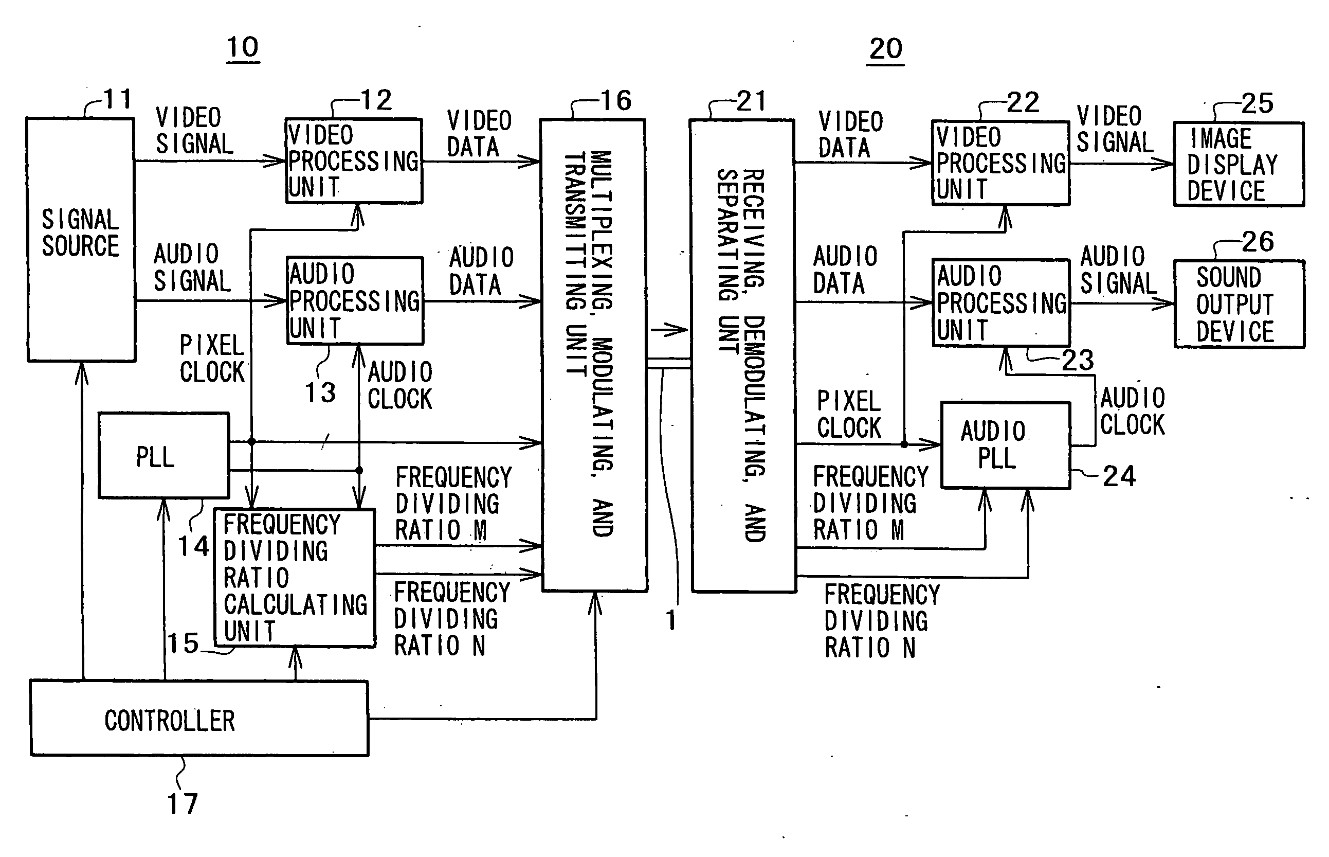
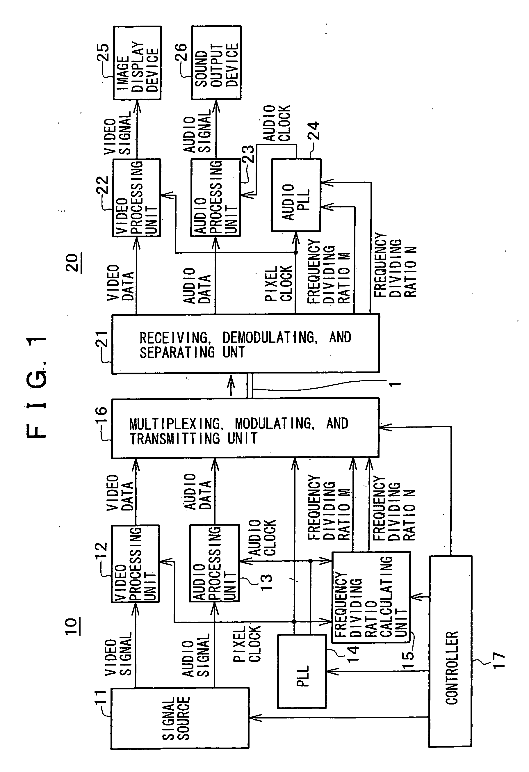
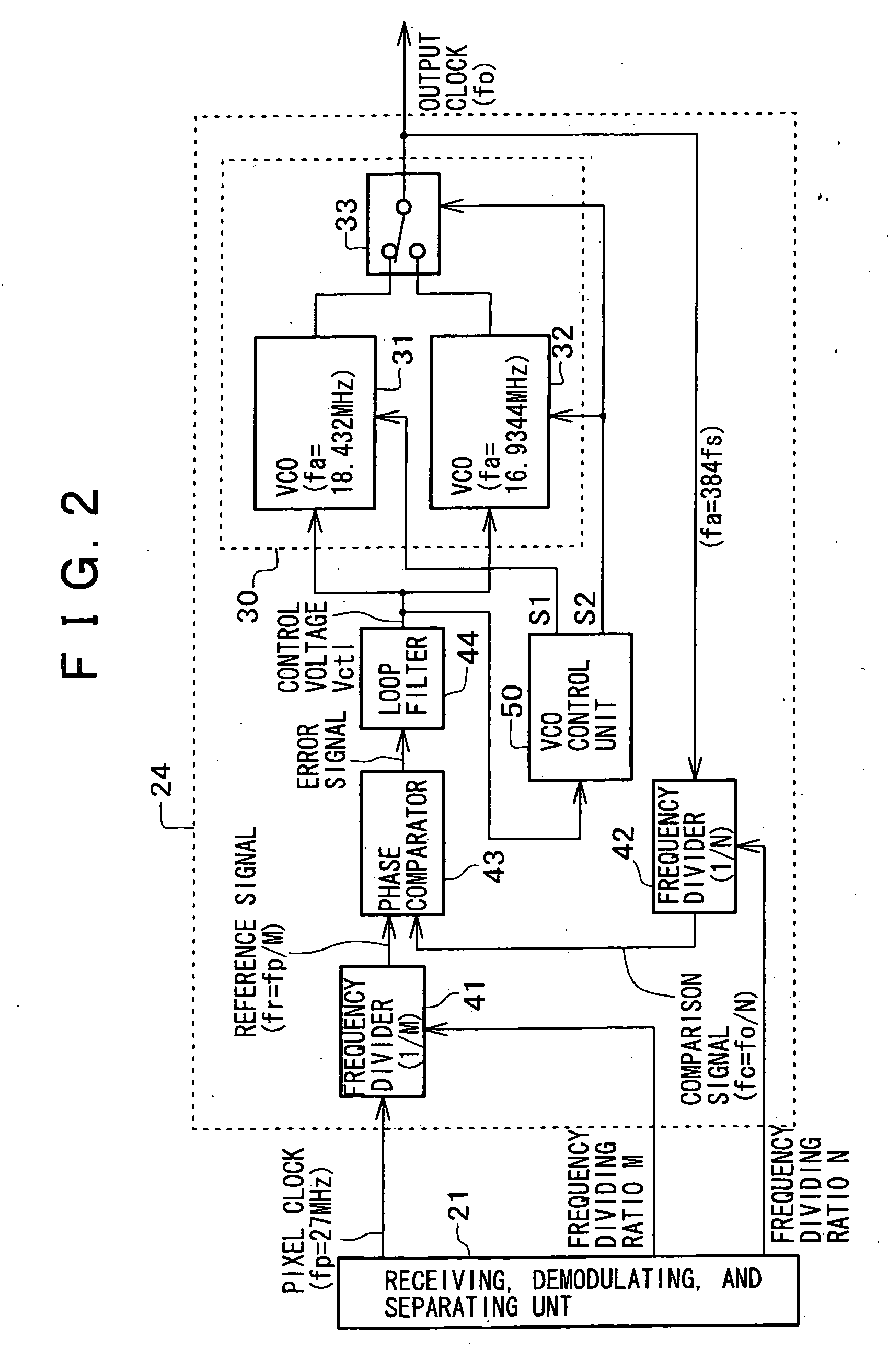
[0038]FIG. 2 shows a first example of the audio PLL 24.

[0039]The audio PLL 24 in this example includes a switching selector circuit 33 and two VCOs 31 and 32 as an oscillating unit 30 so as to deal with the audio sampling frequency fs switched to 48 kHz and 44.1 kHz on the transmitting side 10 as described above.

[0040]The VCO 31 provides an audio clock of a frequency fa=384 fs of 18.432 MHz. The VCO 32 provides an audio clock of a frequency fa=384 fs of 16.9344 MHz. Each of the VCOs 31 and 32 has a narrow oscillation frequency range so as to ensure a certain jitter performance, and has a characteristic of linearly increasing the oscillation frequency as an input control voltage Vctl is increased.

[0041]The audio PLL 24 comprises such an oscillating unit 30, frequency dividers 41 and 42, a phase comparator 43, a loop filter 44, and a VCO control unit 50.

[0042]The frequency divider 41 divides the frequency fp 27 MHz of the pixel clock by M, and thereby pr...

second example fig.4

SECOND EXAMPLE FIG. 4

[0064]While the VCO control unit 50 in the example of FIG. 2 and FIG. 3 detects a change in the audio sampling frequency fs from the control voltage Vctl as the output of the loop filter 44, that is, the error signal as the output of the phase comparator 43, and changes the oscillation frequency range of the oscillating unit 30, the VCO control unit 50 may be configured to detect a change in the audio sampling frequency fs from the oscillation frequency of the oscillating unit 30, that is, the frequency fo of the output clock of the oscillating unit 30, and change the oscillation frequency range of the oscillating unit 30.

[0065]FIG. 4 shows an example in this case. A VCO control unit 50 in this example comprises a frequency discriminator circuit 56, two comparators 57 and 58, and a state retaining RS flip-flop 55.

[0066]The frequency discriminator circuit 56 discriminates the frequency fo of the output clock of the oscillating unit 30. The frequency discriminator...


PUM

PropertyMeasurementUnit
frequencyaaaaaaaaaa
frequency faaaaaaaaaaa

Abstract

Letting fp be the frequency of a pixel clock, fs be the audio sampling frequency, and fa be the frequency of an audio clock to be reproduced, fa=384 fs=(N / M)fp, where N and M are frequency dividing ratios between the pixel clock and the audio clock of a frequency corresponding to the audio sampling frequency. When fs=48 kHz, M=27000 and N=18432, and when fs=44.1 kHz, M=30000 and N=18816. A VCO control unit detects a change in the audio sampling frequency fs from a control voltage Vctl output from a loop filter or from the frequency fo of an output clock of an oscillating unit, and then selects one of at least two VCOs.

Description

CROSS-REFERENCE TO RELATED APPLICATIONS[0001]This application is a divisional of U.S. application Ser. No. 10 / 910,908, filed on Aug. 4, 2004, the disclosure of which is incorporated herein by reference.BACKGROUND OF THE INVENTION[0002]The present invention relates to a digital transmission system in which audio data and content data, such as video data and the like other than the audio data, are transmitted from a transmitting side to a receiving side and then processed on the receiving side, and a device for reproducing an audio clock, which device is provided on the receiving side of the digital transmission system.[0003]A standard referred to as a DVI (Digital Video Interface) standard has been considered as a standard for transmitting a video signal from a signal source, such as a video disk reproducing device, a video tape reproducing device, or a personal computer, as digital video data.[0004]In this DVI standard, a video signal is transmitted as data digitized in pixel units ...

Claims


Application Information

Patent Timeline
Patent Type & Authority Applications(United States)
IPC IPC(8): H03L7/00H04N5/04G11B20/10G11B20/14H03L7/087H03L7/099H03L7/10H03L7/18H04J3/06H04L7/033H04N5/60H04N7/08H04N7/081H04N7/62H04N21/41H04N21/43
CPCH03L7/087H03L7/099H03L7/10H03L7/113H04N21/4305H03L2207/06H04J3/0685H04N5/602H04N21/4122H03L7/18H04N5/04
Inventor MIYAMOTO, MASARU
Owner SONY CORP
Why Eureka
Try Eureka