
Light diffuser plate, surface emission light source apparatus and liquid crystal display

Inactive Publication Date: 2008-05-29
SUMITOMO CHEM CO LTD
View PDF6 Cites 15 Cited by
  • Summary
  • Abstract
  • Description
  • Claims
  • Application Information

AI Technical Summary

Benefits of technology

[0007]The present invention has been conceived with the background described above, and has an object of providing a light diffuser plate, a surface emission light source apparatus and a liquid crystal display apparatus that are capable of preventing the generation of annoying noise from the area of contact between the light diffuser plate and the lamp box.

Problems solved by technology

The light diffuser plate described above is fastened in the state of making contact with the front surface of the frame of the lamp box, and therefore annoying noise may be generated as the front surface of the frame and the light diffuser plate rub against each other.
For example, when the power supply is turned on, the light diffuser plate expands due to rising temperature within the surface emission light source apparatus, thus resulting in the generation of annoying noise as the front surface of the frame and the light diffuser plate rub against each other.
Generation of annoying noise is conspicuous in the case where the frame of the lamp box is made of polycarbonate.

Method used


Image

  • Light diffuser plate, surface emission light source apparatus and liquid crystal display
  • Light diffuser plate, surface emission light source apparatus and liquid crystal display
  • Light diffuser plate, surface emission light source apparatus and liquid crystal display

Examples


examples

[0121]Examples of the present invention will now be described, although it is understood that the present invention is not limited to these Examples.

Raw Materials

[0122]Translucent resin A: Styrene resin (“HRM40” manufactured by Toyo Styrene Co., Ltd., refractive index 1.59)

[0123]Translucent resin B: MS resin (“MS200NT” manufactured by Nippon Steel Chemical Co., Ltd., refractive index 1.57, styrene / methyl methacrylate=80 parts by mass / 20 parts by mass)

[0124]Light diffusing agent A: Linked PMMA particles (“Sumipex XC1A” manufactured by Sumitomo Chemical Co., Ltd., refractive index 1.49, mean particle size by weight average of 35 μm)

[0125]Light diffusing agent B: Linked siloxane polymer particles (“Torayfil DY33-719” manufactured by Toray Dow Corning Inc., refractive index 1.42, mean particle size by volumetric average of 2 μm)

[0126]Light diffusing agent C: “KE-P50” manufactured by Nippon Shokubai Co., Ltd. (refractive index 1.43, mean particle size of 0.54 μm)

[0127]Light diffusing age...

example a1

[0131]97.0 parts by mass of the translucent resin A and 3.0 parts by mass of the light diffusing agent master batch A were mixed in a dry process, and the mixture was melted and mixed in a first extrusion machine of which the cylinder temperature was set in a range from 190 to 250° C., and was supplied to a feed block. Meanwhile the light diffusing agent master batch B was melted and mixed in a second extrusion machine of which the cylinder temperature was set in a range from 190 to 250° C., and was supplied to the feed block.

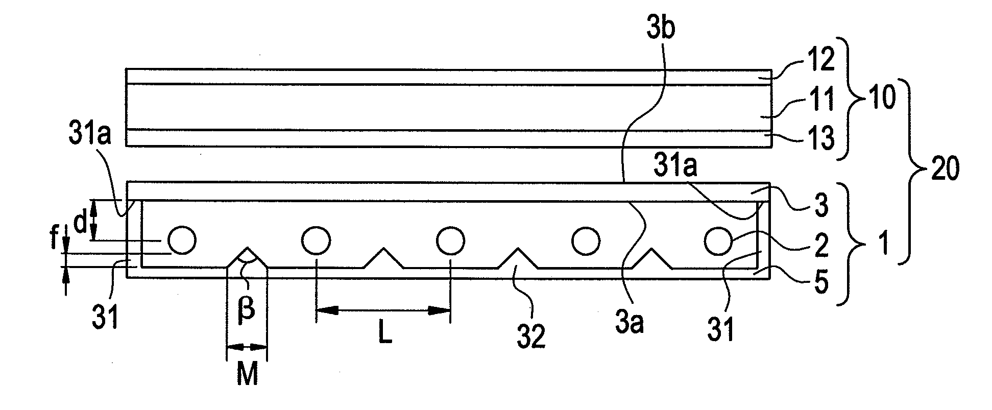
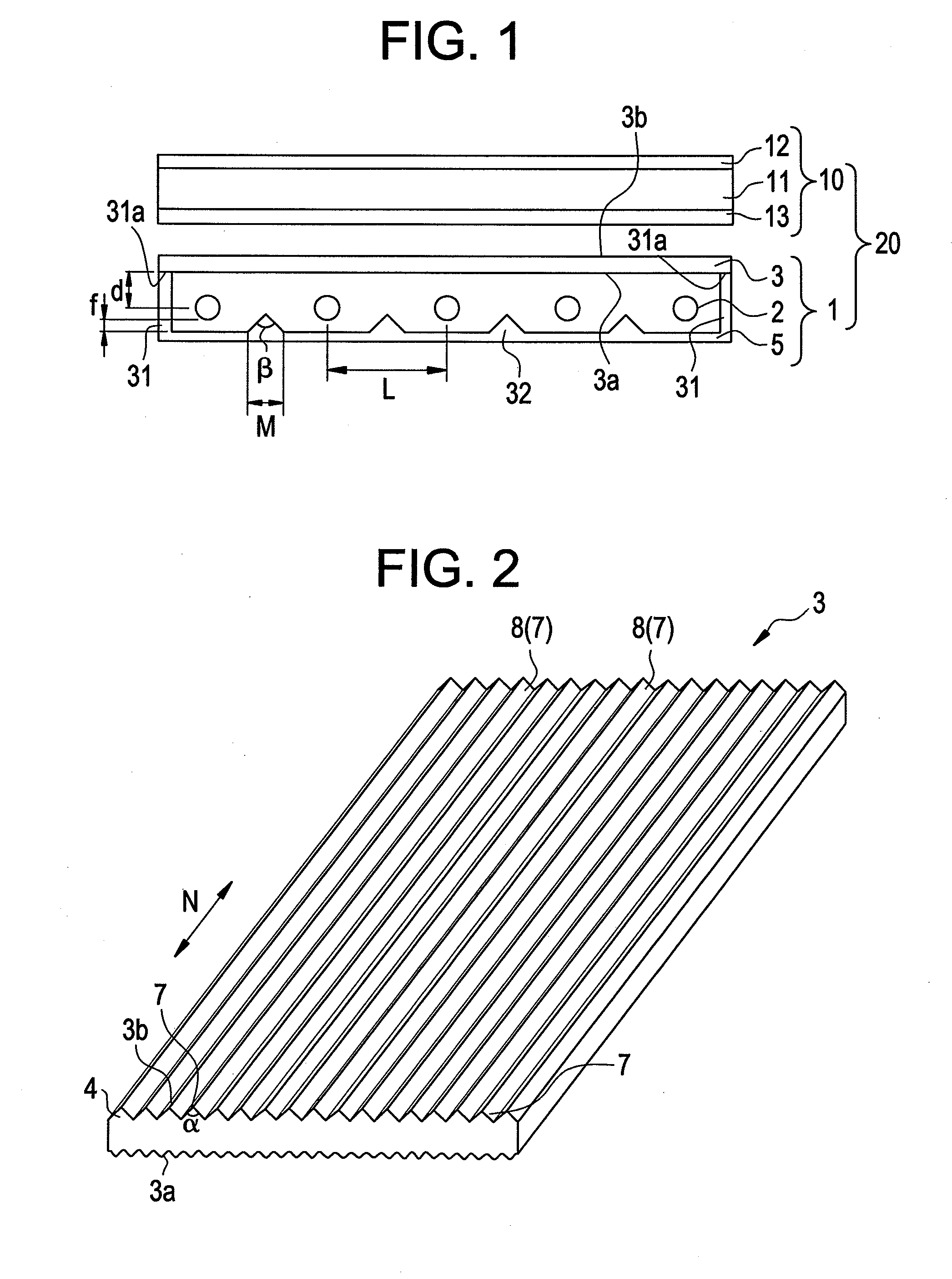
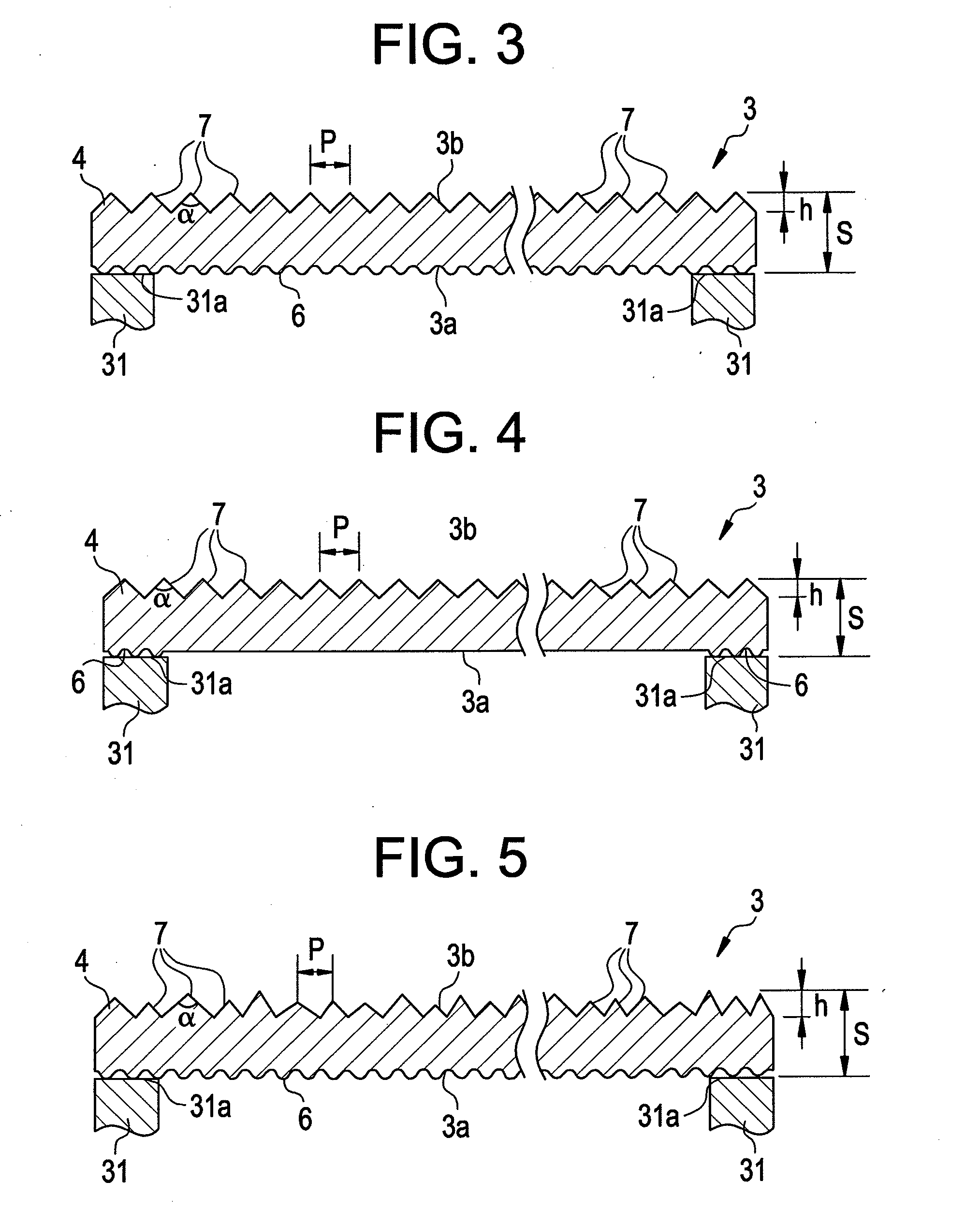
[0132]A coextrusion molding operation was carried out by using a multi-manifold die at an extrusion temperature of 250° C., so that the resin supplied from the first extrusion machine to the feed block would form an intermediate layer (base layer) and the resin supplied from the second extrusion machine to the feed block would form surface layers. These layers were pressed together and cooled by polishing rolls, so as to make a light diffuser plate (3) constitu...

example a2

[0134]97.0 parts by mass of the translucent resin A and 4.5 parts by mass of the light diffusing agent master batch A were mixed in a dry process, and the mixture was melted and mixed in a first extrusion machine of which the cylinder temperature was set in a range from 190 to 250° C., and was supplied to the feed block. Meanwhile the light diffusing agent master batch B was melted and mixed in a second extrusion machine of which the cylinder temperature was set in a range from 190 to 250° C., and was supplied to the feed block.

[0135]A coextrusion molding operation was carried out by using a multi-manifold die at an extrusion temperature of 250° C., so that the resin supplied from the first extrusion machine to the feed block would form an intermediate layer (base layer) and the resin supplied from the second extrusion machine to the feed block would form surface layers. These layers were pressed together and cooled by polishing rolls, so as to make a light diffuser plate (3) consti...


PUM


Abstract

The present invention provides a light diffuser plate, a surface emission light source apparatus and a liquid crystal display apparatus which are capable of preventing the generation of annoying noise in an area of contact between the light diffuser plate and a lamp box.The present invention relates to a surface emission light source apparatus comprising a plurality of light sources disposed at a distance from each other in a lamp box, that is made of a resin and has an open front side, and a light diffuser plate that is made of a resin and is disposed on the front side of the frame of the lamp box so as to close the opening of the lamp box, wherein at least a part of the back surface of the light diffuser plate that makes contact with the front surface of the frame is formed as a matted surface, the matted surface has an arithmetic mean surface roughness Ra in a range from 0.8 to 15 μm and a mean surface irregularity interval Rsm in a range from 100 to 300 μm.

Description

BACKGROUND OF THE INVENTION[0001]1. Field of the Invention[0002]The present invention relates to a light diffuser plate, a surface emission light source apparatus and a liquid crystal display apparatus which are capable of preventing the generation of annoying noise in an area of contact between the light diffuser plate and a lamp box.[0003]In this specification and the claims, the term “arithmetic mean surface roughness Ra” means the arithmetic mean surface roughness Ra measured according to JIS B0601-1994, and the term “mean surface irregularity interval Rsm” means the mean surface irregularity interval Rsm measured according to JIS B0601-1994.[0004]2. Description of the Related Art[0005]Such a liquid crystal display apparatus is known, for example, that has a surface emission light source apparatus disposed as the backlight on the lower surface (back surface) of a display section that comprises liquid crystal cell and a pair of polarizer plates disposed on the top and bottom side...

Claims


Application Information

Patent Timeline
IPC IPC(8): F21V11/00F21V1/00G02F1/1335
CPCF21V5/02G02F1/133604G02F2001/133607G02F1/133608G02F1/133606G02F1/133607G02F1/1335
Inventor OKU, HISANORIIYAMA, HIRONOBU
Owner SUMITOMO CHEM CO LTD
Features
  • Generate Ideas
  • Intellectual Property
  • Life Sciences
  • Materials
  • Tech Scout
  • Unparalleled Data Quality
  • Higher Quality Content
  • 60% Fewer Hallucinations
Learn More