Electromagnetic interference shielding apparatus for signal transceiver

a shielding apparatus and signal transceiver technology, applied in shielding materials, electrical apparatus casings/cabinets/drawers, rack/frame construction, etc., can solve the problems of ineffective shielding, ineffective stopping of high-frequency signals, and inability to effectively shield, so as to prevent the permeation of external moisture, prevent the leakage of internal high-frequency signals, and facilitate assembly

Active Publication Date: 2008-05-29
MICROELECTRONICS TECH INC
View PDF12 Cites 9 Cited by
  • Summary
  • Abstract
  • Description
  • Claims
  • Application Information

AI Technical Summary

Benefits of technology

[0005]One aspect of the present invention is to provide an electromagnetic interference shielding apparatus for a signal transceiver, which employs two folded-edge mechanisms coupled together and an adhesive, so as to effectively stop the leakage of internal high-frequency signals and interference of external noises, and to form a sealed connection to prevent the permeation of external moisture.
[0006]Another aspect of the present invention is to provide an electromagnetic interference shielding apparatus for a signal transceiver, which employs the coupling of two folded-edge mechanisms and an adhesive directly used to make the two folded-edge mechanisms form the electromagnetic interference shielding apparatus. The electromagnetic interference shielding apparatus has the advantages of easy assembly, easy disassembly, and low material cost.
[0007]The present invention discloses an electromagnetic interference shielding apparatus, which is applicable to a signal transceiver, and includes a metal cover, an adhesive, and a chassis having a waveguide output hole. The metal cover includes a first combination portion having a first curved section is disposed on an edge of the metal cover. A second combination portion having a second curved section corresponding to the first combination portion is disposed on an edge of the chassis, and the chassis carries the signal transceiver. The adhesive combines the first combination portion and the second combination portion. A transmitted signal of the signal transceiver is outputted through the waveguide output hole. The first combination portion and the second combination portion form a curved space that is used with the adhesive to prevent leakage of the transmitted signal and the interference of external noises.

Problems solved by technology

Generally speaking, if is difficult for microwave signals transmitted between the earth and artificial satellites to pass through walls, roofs, or even glass windows.
However, the conventional shielding apparatus 10 has the following disadvantages: (1) the cover 11 and the chassis 12 are generally fabricated by die casting; when they are combined by the plurality of screws 14 and the O-ring 13, the slit between rough combined surfaces 111 and 121 cannot effectively stop the leakage of high-frequency signals (e.g., signals belonging to the Ku band, C band, or Ka band), and cannot effectively shield the interference of external noises; and (2) when disassembling or assembling the upper cover 11 and the chassis 12, the screws 14 must be loosened or fastened one by one, so much time and cost has to be spent during assembly and testing.

Method used


Image

  • Electromagnetic interference shielding apparatus for signal transceiver
  • Electromagnetic interference shielding apparatus for signal transceiver
  • Electromagnetic interference shielding apparatus for signal transceiver

Examples


Embodiment Construction

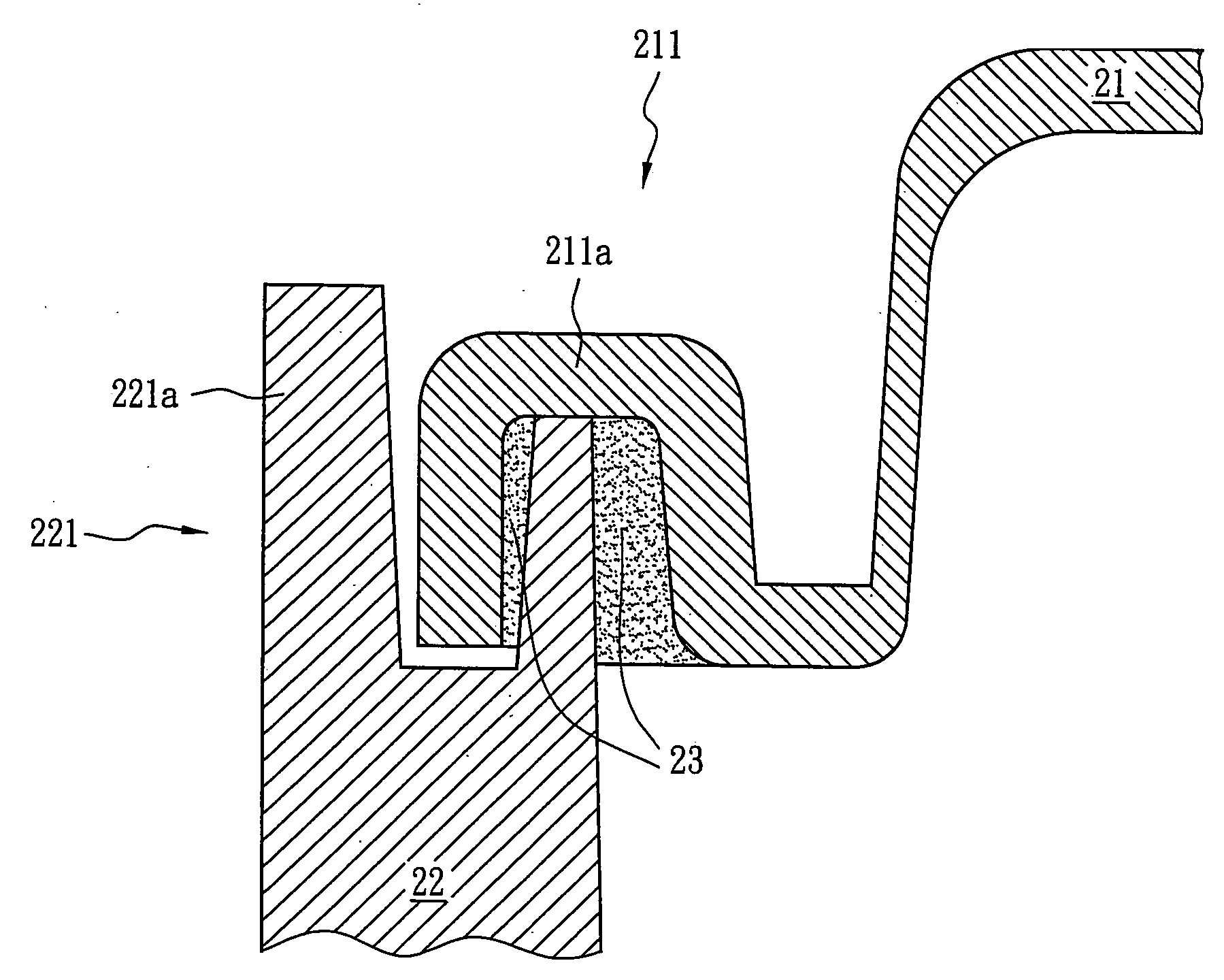
[0015]FIG. 2 shows an electromagnetic interference shielding apparatus 20 according to an embodiment of the present creation. The electromagnetic interference shielding apparatus 20 includes a metal cover 21, a chassis 22 having a waveguide output hole 25, two recess portions 212, and an adhesive 23 (refer to FIG. 6(b)). FIGS. 3 and 4 are sectional views of the metal cover 21 and the chassis 22, respectively, taken along a sectional line A-A′ of FIG. 2. FIG. 5 is a schematic combination view of FIGS. 3 and 4. For the convenience of illustration, FIGS. 6(a) and 6(b) are partial enlarged views of region B in FIG. 5; FIG. 6(a) shows a situation in which the adhesive 23 is not included, whereas FIG. 6(b) shows a case in which the adhesive 23 is included.

[0016]Referring to FIGS. 2, 3, and 6(a), a first combination portion 211 having a first curved section 211a is disposed on an edge of the metal cover 21. In this embodiment, the metal cover 21 is a rectangular flat structure having four ...


PUM


Abstract

An electromagnetic interference shielding apparatus for a signal transceiver employs two folded-edge mechanisms coupled together and an adhesive. The electromagnetic interference shielding apparatus includes a metal cover, a chassis having a waveguide output hole, and an adhesive. A first combination portion having a first curved section is disposed on an edge of the metal cover. A second combination portion having a second curved section corresponding to the first combination portion is disposed on an edge of the chassis. The adhesive is used to combine the first combination portion and the second combination portion. The waveguide output hole outputs a signal transmitted by the signal transceiver. The first combination portion and the second combination portion form a curved space that is used with the adhesive to prevent leakage of the transmitted signal and the interference of external noises.

Description

BACKGROUND OF THE INVENTION[0001]1. Field of the Invention[0002]The present invention relates to an electromagnetic interference shielding apparatus for a signal transceiver. More particularly, the present invention relates to an electromagnetic interference shielding apparatus applicable to a high-frequency signal transceiver.[0003]2. Description of the Related Art[0004]Generally speaking, if is difficult for microwave signals transmitted between the earth and artificial satellites to pass through walls, roofs, or even glass windows. Therefore, satellite signal transceivers are located outdoors with antennas pointing directly at artificial satellites to obtain optimal transmission efficiencies. FIG. 1(a) shows a conventional shielding apparatus 10 of a block upconverter (BUC) accommodating an outdoor satellite signal transceiver (not shown), which is mainly used to protect the outdoor satellite signal transceiver from damage caused by the external environment (e.g., rain, moisture,...

Claims


Application Information

Patent Timeline
Patent Type & Authority Applications(United States)
IPC IPC(8): H05K9/00
CPCH05K9/0073H05K9/006H05K5/062
Inventor CHEN, RUEI YUENKOU, FANG YUHUANG, YI HSIANG
Owner MICROELECTRONICS TECH INC
Why Eureka
Try Eureka