
Seismic streamer array

Active Publication Date: 2008-05-29
OPTOPLAN
View PDF55 Cites 71 Cited by
  • Summary
  • Abstract
  • Description
  • Claims
  • Application Information

AI Technical Summary

Benefits of technology

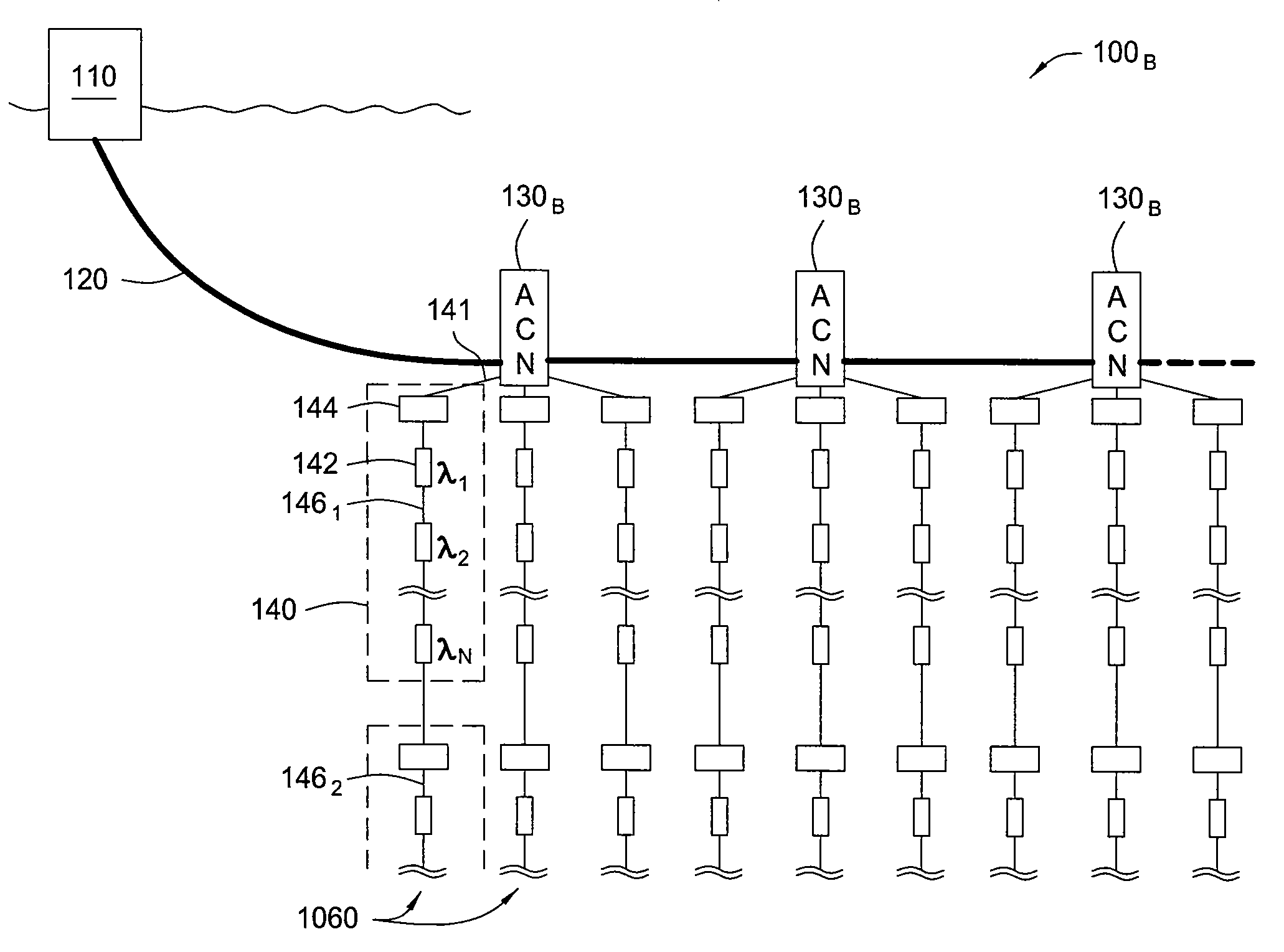
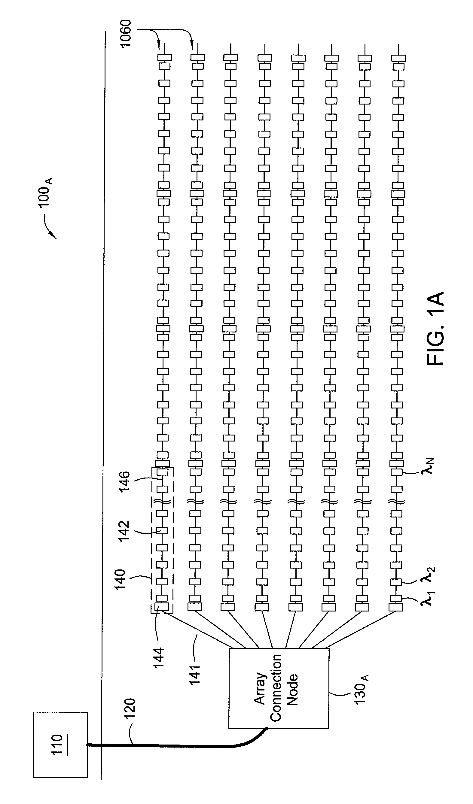
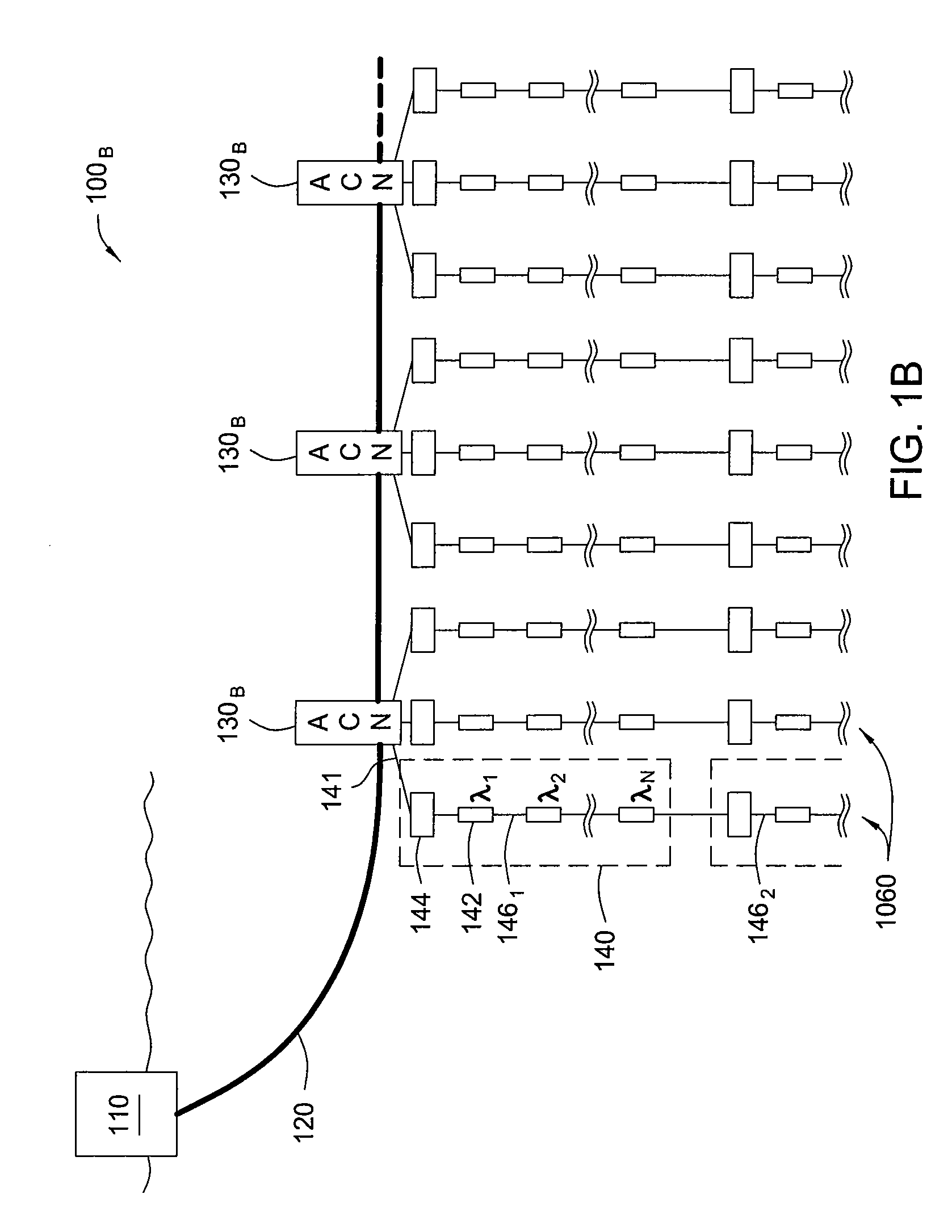
[0013]One embodiment provides a seismic sensing system generally including one or more series of seismic sensor stations and instrumentation. Each station houses a plurality of optical sensors sharing a common wavelength, the common wavelength being different for each station in a same series. The instrumentation is coupled to the series of seismic sensor stations and configured to interrogate sensors housed in each station using time division multiplexing (TDM) and to interrogate sensors housed in different sensor stations in each series using wavelength division multiplexing (WDM).
[0014]Another embodiment provides an array of seismic sensor stations generally including at least one array connection module and a plurality of array cables extending from the array connection module. Each array cable includes a series of array cable modules and a multi-fiber lead cable, each array cable module including a series of seismic sensor stations, each station housing a plurality of optical sensors sharing a common wavelength, the common wavel

Problems solved by technology

In such systems, a light source generates interrogating light pulse pairs (spaced apart in accordance with a length of fiber between reflectors in each interferometric sensor), resulting in interfering signals reflected back to the surface.
As the total number of sensors in the arrays increases in high channel count (HCC) applications, it becomes a challenge to interrogate each sensor using a manageable number of optical fibers run to and from surface instrumentation.
While multiplexing techniques, such as wavelength division multiplexing (WDM) and time division multiplexing (TDM) are well known, there are typically limits to each.
On the one hand, there is a practical limit as to how many sensors may be interrogated by a single fiber, due to a limited number of wavelengths and limitations on total transmitted power per fiber set by optical nonlinear interactions.
On the other hand, TDM of multiple interferometric sensors using reflectors of a common wavelength are subject to unwanted reflections between sensor elements (causing cross-talk).
In some cases, in order to generate sufficient optical power to interrogate a high number of sensors in an OBS array, relatively expensive components, such as remotely pumped sources and optical amplifiers may be used.
Unfortunately, such remotely deployed components are relatively expensive and typically require special pressure sealed housings to be operated at the high pressures seen at the ocean bottom.
Replacing failing components remotely located subsea is an expensive and time-consuming process.
Packaging and deployment of OBS sensor arrays also create challenges in order to achieve efficient coupling of the seismic signals to the respective sensors.
Cutting and splicing data transmission cables / fibers within the cable array at each of the sensor stations increases time and cost while decreasing reliability.

Method used


Image

  • Seismic streamer array
  • Seismic streamer array
  • Seismic streamer array

Examples


Embodiment Construction

[0036]Embodiments of the invention generally relate to seismic sensor systems and sensor station topologies, as well as corresponding cable and sensor station components, manufacturing and deployment techniques. For some embodiments, networks of optical ocean bottom seismic (OBS) stations are provided, in which sensor stations are efficiently deployed in a modular fashion as series of array cable modules deployed along a multi-fiber cable.

[0037]Interferometric sensors within each sensor station may share a common wavelength and be interrogated in a time division multiplexed (TDM) manner. Each sensor station, however, may utilize a different wavelength for its sensors, allowing multiple stations in series within an array cable module to be interrogated on a common “sensor” fiber utilizing wavelength division multiplexing (WDM).

[0038]For some embodiments, within each array cable module, only the sensor fiber is connected to the sensors at each station, while a multi-fiber tube “bypass...


PUM


Abstract

Seismic sensor systems and sensor station topologies, as well as corresponding cable and sensor station components, manufacturing and deployment techniques are provided. For some embodiments, networks of optical ocean bottom seismic (OBS) stations are provided, in which sensor stations are efficiently deployed in a modular fashion as series of array cable modules deployed along a multi-fiber cable.

Description

CROSS-REFERENCE TO RELATED APPLICATIONS[0001]This is a continuation-in-part of co-pending U.S. patent application Ser. No. 11 / 381,880 filed May 5, 2006, which is hereby incorporated by reference.BACKGROUND OF THE INVENTION[0002]1. Field of the Invention[0003]Embodiments of the invention generally relate to seismic sensing and, in particular, to components and techniques for deploying and interrogating arrays of seismic sensors, such as in ocean bottom seismic sensing (OBS) applications.[0004]2. Description of the Related Art[0005]Marine seismic exploration surveys for the exploration and monitoring of hydrocarbon producing zones and reservoirs utilize seismic cables having sensor arrays, i.e., a plurality of sensor stations interconnected by sections of cable. The cable arrays may include a large number of sensor stations (e.g., several hundreds or thousands) and may be buried in a predetermined pattern on the ocean floor. Optical sensors may be particularly well suited for ocean bo...

Claims


Application Information

Patent Timeline
IPC IPC(8): G01V1/38
CPCG01D5/35383G01H9/004G01V1/20G01V2210/1427G01V1/226G01V1/3808G01V1/201G01D5/35316G01D5/268G01D5/32G01V1/22G01V1/38G01V8/20G01V8/22G01V8/24G01V1/16G01V1/3852
Inventor RONNEKLEIV, ERLENDWAAGAARD, OLE HENRIKNAKSTAD, HILDEBERG, ARNE
Owner OPTOPLAN
Learn More