Method of Manufacturing Semiconductor Device

Inactive Publication Date: 2008-05-29
DONGBU HITEK CO LTD
View PDF3 Cites 3 Cited by
  • Summary
  • Abstract
  • Description
  • Claims
  • Application Information

AI Technical Summary

Benefits of technology

[0007]Embodiments of the present invention provide a method of manufacturing a semiconductor device without depositing a barrier layer. The method is capable of allowing for reduced semiconductor device size and improved line reliability.

Problems solved by technology

However, copper often diffuses into the insulating layer of the semiconductor device because of its high diffusivity.
This can lead to a short-circuit between lines.
Though semiconductor devices have been decreasing in size, forming a barrier layer in order to use a copper line typically limits size reduction of the semiconductor devices.
However, forming lines with a small width increases resistance and lowers line reliability.

Method used


Image

  • Method of Manufacturing Semiconductor Device
  • Method of Manufacturing Semiconductor Device
  • Method of Manufacturing Semiconductor Device

Examples


Embodiment Construction

[0011]When the terms “on” or “over” are used herein, when referring to layers, regions, patterns, or structures, it is understood that the layer, region, pattern or structure can be directly on another layer or structure, or intervening layers, regions, patterns, or structures may also be present. When the terms “under” or “below” are used herein, when referring to layers, regions, patterns, or structures, it is understood that the layer, region, pattern or structure can be directly under the other layer or structure, or intervening layers, regions, patterns, or structures may also be present.

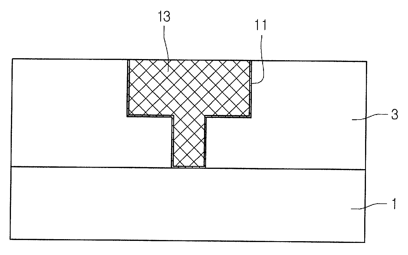
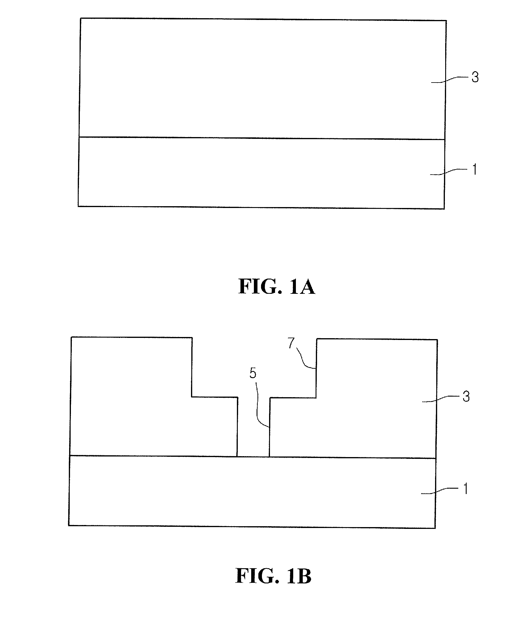
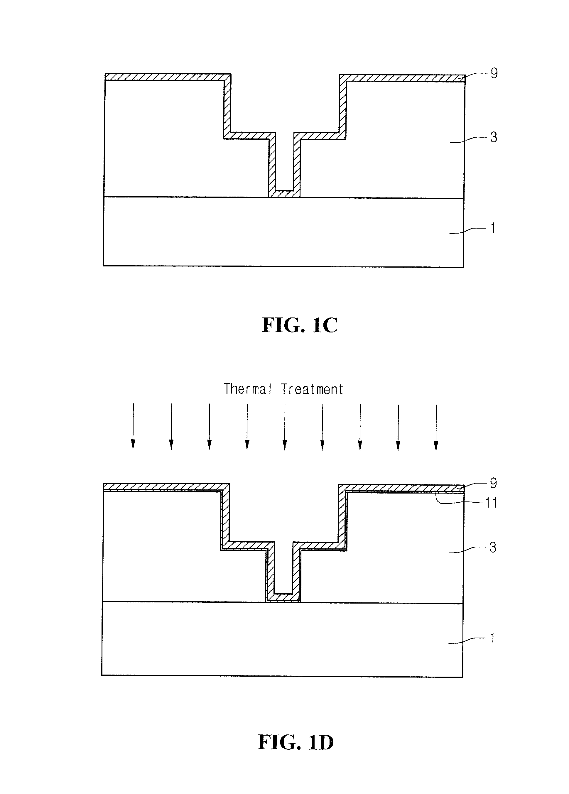
[0012]Referring to FIG. 1A, a semiconductor substrate 1 can be provided and can include a device module having a predetermined function. The device module can be any suitable module known in the art, for example, a memory device or a logic circuit. In an embodiment, the device module can be provided on the semiconductor substrate 1 to perform a driver function for providing a predetermined sign...


PUM


Abstract

A method manufacturing a semiconductor device is provided. Cost can be reduced and line reliability can be improved since a step for depositing a barrier metal is not required. An interlayer insulating layer, including a contact hole, can be formed on a semiconductor substrate. A seed layer, including a first metal material and at least one additive, can be formed on the interlayer insulating layer. A thermal treatment can be performed on the seed layer to form an interface layer under the seed layer, and a second metal material can be deposited on the seed layer to form a metal line.

Description

CROSS-REFERENCE TO RELATED APPLICATION[0001]The present application claims the benefit under 35 U.S.C. § 119 of Korean Patent Application No. 10-2006-0117459, filed Nov. 27, 2006, which is hereby incorporated by reference in its entirety.BACKGROUND[0002]Semiconductor devices typically include interconnection lines in a multi-layered structure to allow for a high degree of integration. The lines are often formed of a metal material in order to make an electrical connection through an insulating layer, such as a pre-metallic dielectric (PMD) layer or an inter-metallic dielectric (IMD) layer.[0003]Generally, aluminum (Al) or copper (Cu) are used as the metal material of the lines.[0004]However, copper often diffuses into the insulating layer of the semiconductor device because of its high diffusivity. This can lead to a short-circuit between lines. Therefore, in order to attempt to inhibit the diffusion of copper, a barrier layer is typically formed before a copper line is formed.[0005...

Claims


Application Information

Patent Timeline
IPC IPC(8): H01L21/4763
CPCH01L21/76843H01L21/76873H01L21/76867H01L21/76864H01L21/28
Inventor HONG, JI HO
Owner DONGBU HITEK CO LTD
Why Eureka
Try Eureka