
Hybrid optical integrator assembly and optical system comprising it

Active Publication Date: 2017-03-30
GUANGZHOU HAOYANG ELECTRONICS CO LTD
View PDF6 Cites 1 Cited by
  • Summary
  • Abstract
  • Description
  • Claims
  • Application Information

AI Technical Summary

Benefits of technology

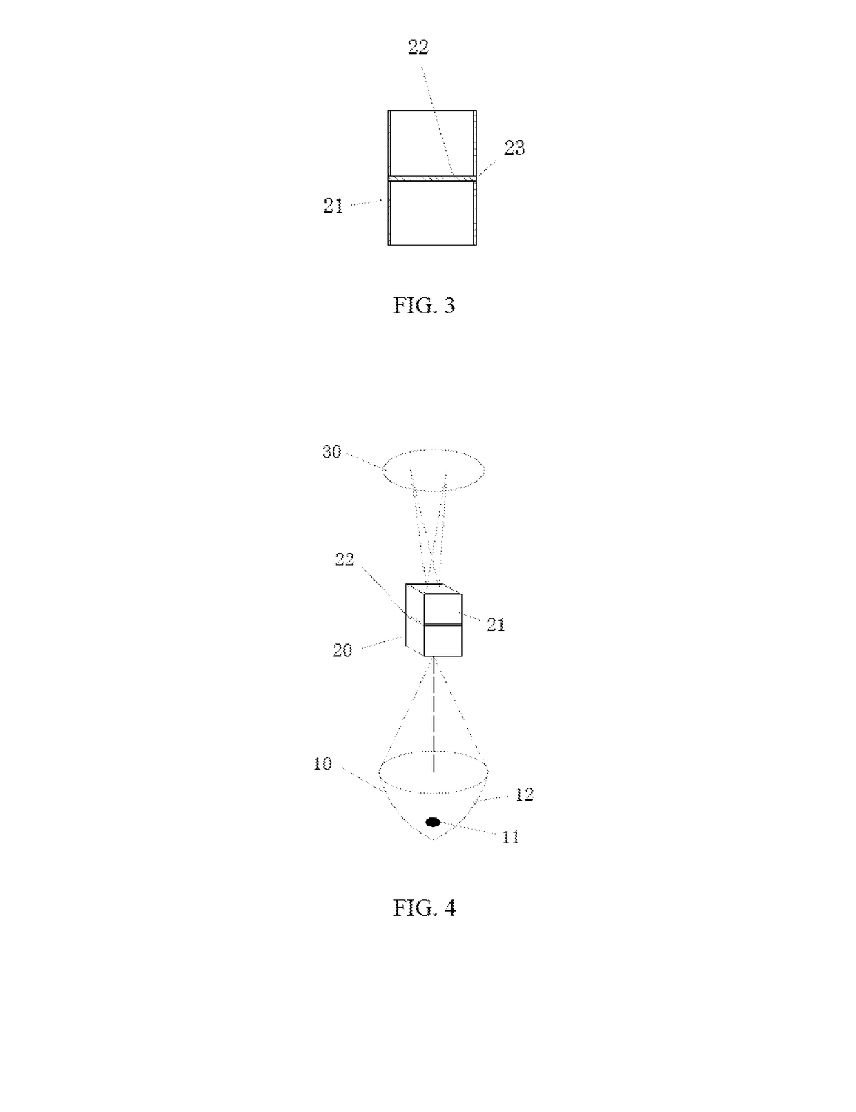
The present invention provides a solution to improve the efficiency and uniformity of lighting in optical systems. This is achieved by integrating an optical integrator with a scattering element, which scatters the light beams and performs a uniforming process. This results in a brighter and more uniform beam of light, while also reducing the size of the optical system. Additionally, the scattering element helps to achieve both overall and local uniformity of the lighting, improving the quality of the final image. The invention also includes the use of a scattering flat glass sheet with optical films to increase transmittance, and a simultaneous reduction in the size of the optical integrator. These technical effects make the optical system lighter, handier, and provide sufficient space for other components.

Problems solved by technology

In an optical system of the field of stage lighting, due to various influencing factors, formed light spots projected by stage lighting are often found in problems of non-uniform luminance (overall non-uniform), black spots (locally non-uniform) and so forth when stage lighting is used for projecting light beam toward a stage or other target regions.
In normal conditions, however, if only the optical integrator is used, such as a light-guiding pipe or a light-guiding rod, the required length is relatively long, since the uniformity problems of the light spots eventually projected by the light-guiding pipe or light-guiding rod are closely bound up with the size of the light-guiding rod.
The optical integrator occupies more space, causing that both other light source modules and the optical integrator (e.g. light-guiding pipe or light-guiding rod and so forth) need to be designed to avoid the optical integrator, such that it fails to obtain the ideal design.
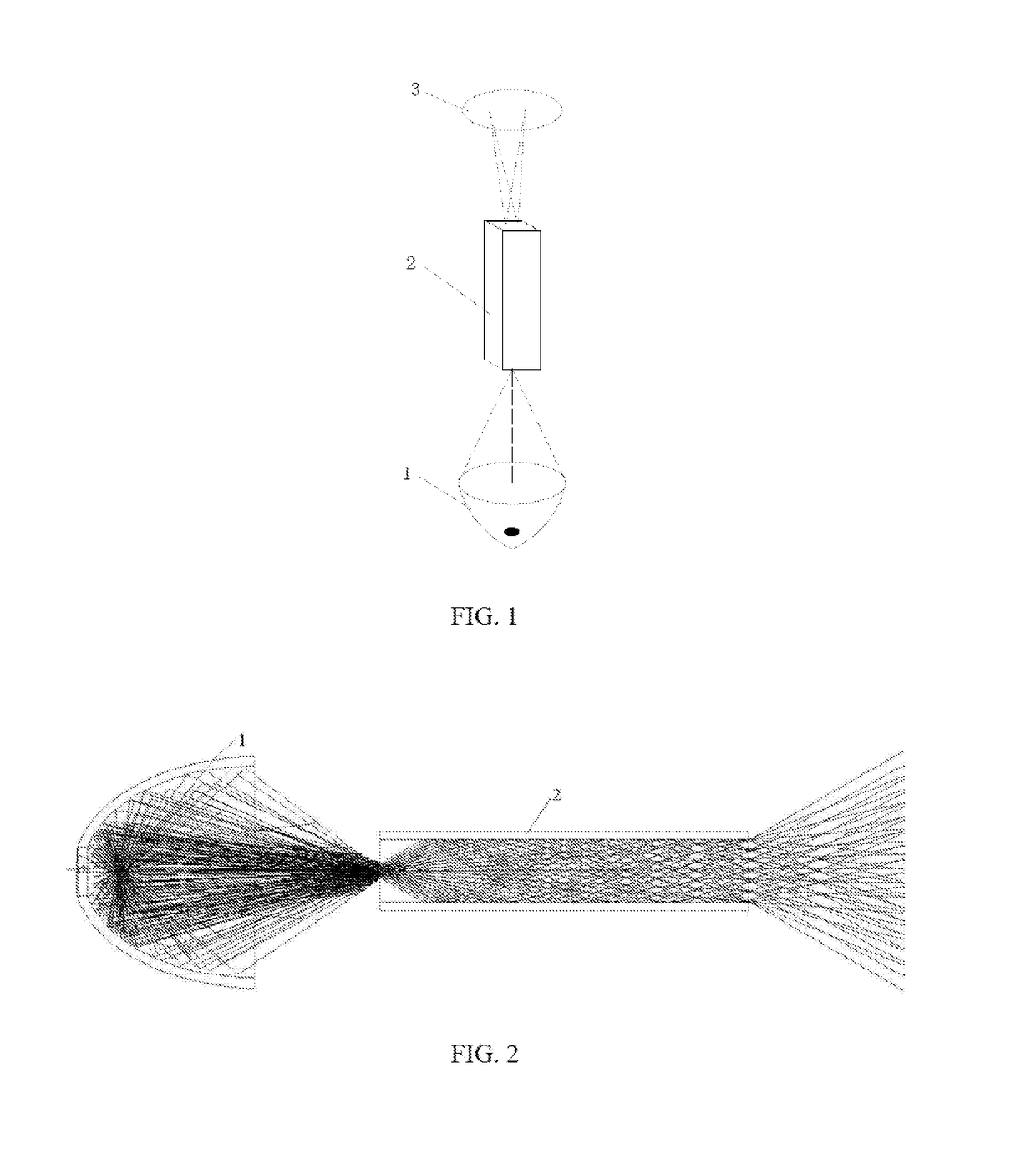
Moreover, as shown in FIG. 2, the light beam processed with the existing optical integrator still shines according to certain rule and direction, without realizing complete scattering, and there often will be a locally non-uniform phenomenon in the formed light spots.

Method used


Image

  • Hybrid optical integrator assembly and optical system comprising it
  • Hybrid optical integrator assembly and optical system comprising it
  • Hybrid optical integrator assembly and optical system comprising it

Examples


embodiment 1

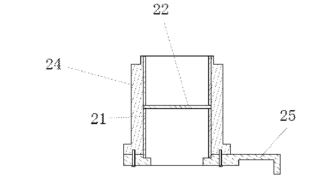
[0030]As shown in FIG. 3, the present invention discloses a hybrid optical integrator assembly, which comprises an optical integrator 21, wherein, the hybrid optical integrator assembly further comprises a scattering element 22 which is disposed on any cross section of the optical integrator and performs scattering process to a light beam passing through. In the present invention, by means of disposing the scattering element 22 in the optical integrator 21, the scattering process of the light could be improved within the optical integrator or an end of the optical integrator, such that the light uniforming efficiency of the light becomes higher, and that a processing path of the optical integrator is shortened under the premise of meeting certain illumination uniformity, so that the optical integrator has a smaller size. In addition, as a separate optical integrator, after the diverging light entering into which and being processed, the brightness of the middle light spots of the ou...

embodiment 2

[0043]The structure of the present embodiment is similar to that of the embodiment 1, with differences lying in that, said optical integrator 21 is a solid light-guiding rod. As shown in FIG. 11 and in FIG. 12, said scattering flat glass sheet may be embedded onto a cross section of a middle part inside the solid light-guiding rod, and the scattering flat glass sheet may be perpendicular to a central axis of the solid light-guiding rod, so that the light beam emitted by the light source passes through the scattering flat glass sheet, and then is shot by an output port of the solid light-guiding rod.

[0044]When the optical integrator adopts the solid light-guiding rod, in addition to that the above-described scattering flat glass sheet may be embedded into onto the cross section of the middle part inside the solid light-guiding rod, the solid light-guiding rod may also be separated into two parts as a two-section structure, and a scattering surface is used at a joint surface of two se...

embodiment 3

[0045]The structure of the present embodiment is similar to that of the embodiment 1, with differences lying in that, as shown in FIG. 13 and FIG. 14, said scattering flat glass sheet may also be disposed at an input end or an output end of the optical integrator, and said optical integrator may be a hollow light-guiding pipe or a solid light-guiding rod. When being the solid light-guiding rod, the scattering flat glass sheet may also be substituted as a scattering surface and thereby be directly disposed on the input end or output end.


PUM


Abstract

A hybrid optical integrator assembly and an optical system comprising it. The hybrid optical integrator assembly comprises an optical integrator (21) and a scattering element (22) which is disposed on any cross section of the optical integrator (21) and performs scattering process to a light beam passing through. The hybrid optical integrator assembly is able to shorten a processing path of the optical integrator, so that the optical integrator has a smaller size.

Description

TECHNICAL FIELD[0001]The present invention relates to a hybrid optical integrator assembly and an optical system thereof.BACKGROUND[0002]In an optical system of the field of stage lighting, due to various influencing factors, formed light spots projected by stage lighting are often found in problems of non-uniform luminance (overall non-uniform), black spots (locally non-uniform) and so forth when stage lighting is used for projecting light beam toward a stage or other target regions. To solve the above problems, in the prior art, as shown in FIG. 1, an optical integrator 2, such as a light-guiding pipe or a light-guiding rod, a microlens array, or an atomization piece, is generally disposed between a light source assembly 1 and an object assembly 3 to obtain relatively uniform light spots. Wherein, a concentrated beam is emitted by said light source assembly 1, becomes uniform via the optical integrator assembly 2, and then is shot after entering into the object assembly 3.[0003]In...

Claims


Application Information

Patent Timeline
IPC IPC(8): F21V7/00F21V5/00F21V7/06F21V8/00
CPCF21V7/0091F21V7/06F21V5/002G02B6/0008G02B27/0994G03B21/208
Inventor JIANG, WEIKAI
Owner GUANGZHOU HAOYANG ELECTRONICS CO LTD
Learn More