Laser device

Pending Publication Date: 2022-02-17
MITSUBISHI ELECTRIC CORP
View PDF0 Cites 0 Cited by
  • Summary
  • Abstract
  • Description
  • Claims
  • Application Information

AI Technical Summary

Benefits of technology

The present invention increases the number of light signals and reduces the size of the device configuration required for coherent beam combining by using multiple photodetectors to convert interference light signals into electric signals. The invention generates light phase control signals for phase error compensation on the basis of the electric signals. This results in a higher degree of freedom in the number of interference light signals, leading to a more efficient and effective coherent beam combining process.

Problems solved by technology

In the laser system disclosed in Patent Literature 1, when the number N of signals is large, a configuration of optical components required for multiplexing with local oscillation light is huge disadvantageously.
In addition, when the number N of signals is large, highly accurate adjustment of alignment of each of the collimator (lens array) and the interferometer is required disadvantageously.

Method used


Image

  • Laser device
  • Laser device
  • Laser device

Examples


first embodiment

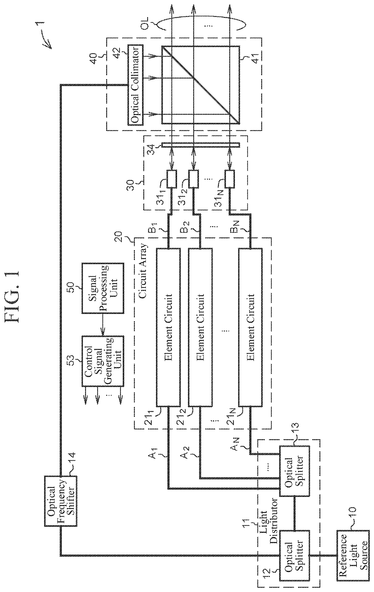
[0023]FIG. 1 is a diagram illustrating a schematic configuration of a laser device 1 of a first embodiment according to the present invention. As illustrated in FIG. 1, the laser device 1 includes: a reference light source 10 for outputting reference laser light having a single frequency; a light distributor 11 for distributing the reference laser light into local oscillation light and N light signals (N is a positive integer of 2 or more); a light frequency shifter 14 for shifting a light frequency of the local oscillation light; a circuit array 20 that functions as an optical phased array for generating N phase modulated light signals (phase control light signals) by applying variable phase modulation (variable phase control) to each of the N light signals; a front optical system 30 for collimating the N phase modulated light signals input from element circuits 211 to 21N; a beam combining optical system (reflective optical system) 40 for outputting a bundle OL of N collimated lig...

second embodiment

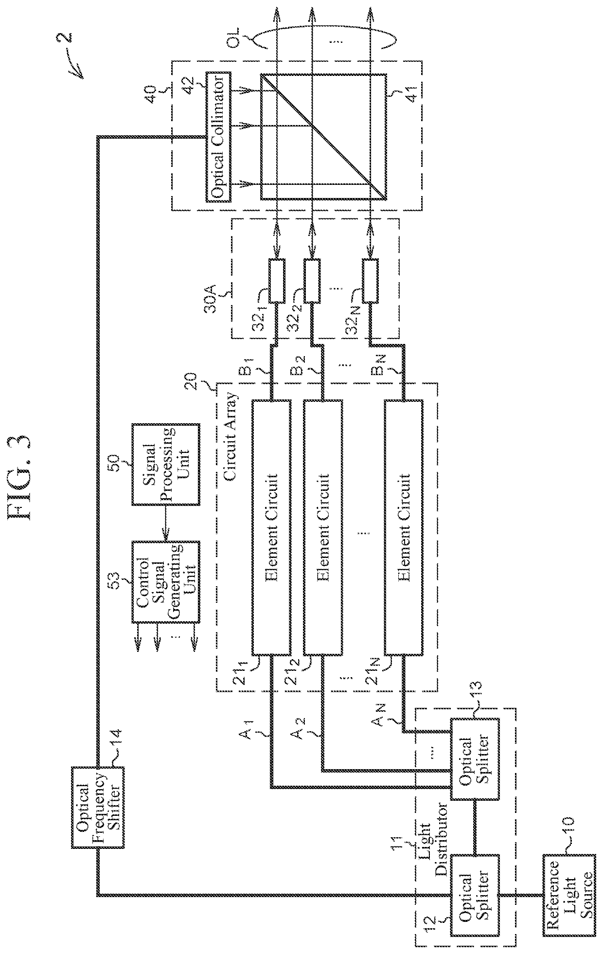
[0041]Next, a second embodiment according to the present invention will be described. FIG. 3 is a diagram illustrating a schematic configuration of a laser device 2 of the second embodiment according to the present invention. As described above, in the first embodiment, the partial reflector 34 is used for generating partially reflected light signals. On the other hand, in the present embodiment, partially reflected light signals are generated without using the partial reflector 34.

[0042]A configuration of the laser device 2 illustrated in FIG. 3 is the same as the configuration of the laser device 1 of the first embodiment except that a front optical system 30A is included instead of the front optical system 30 of the first embodiment.

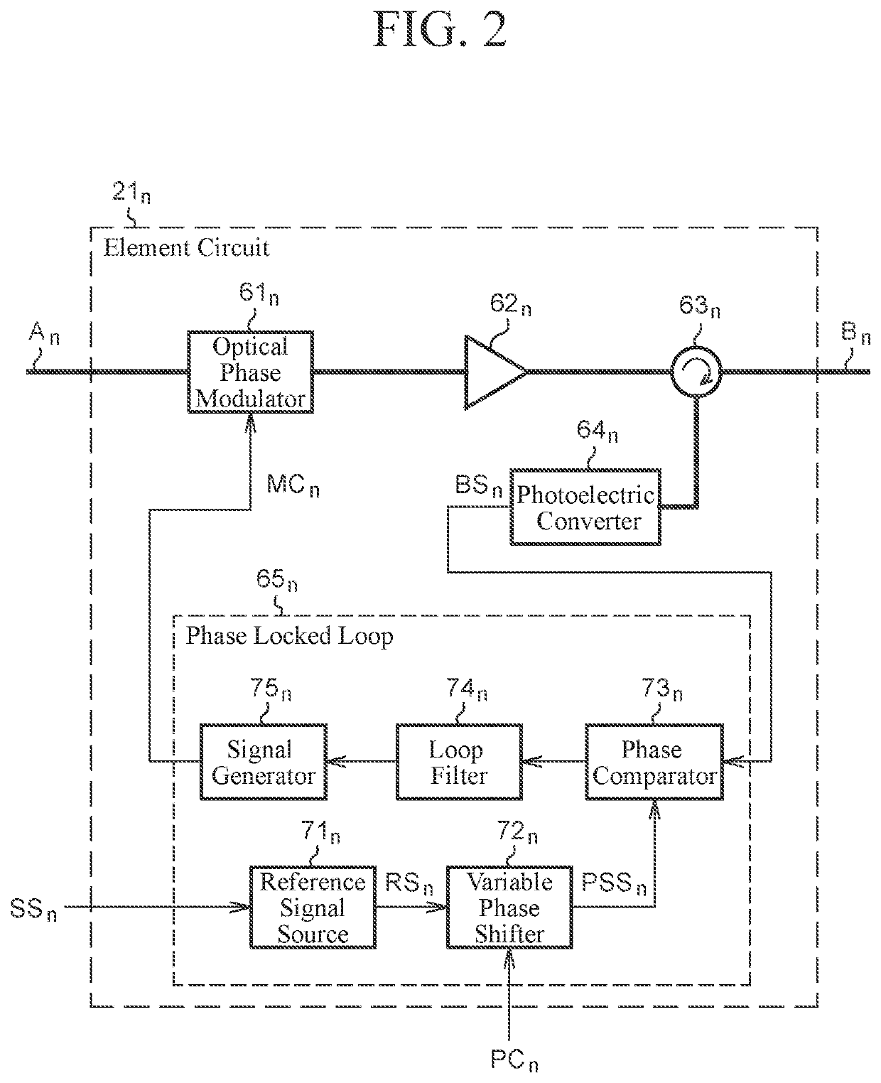
[0043]The front optical system 30A illustrated in FIG. 3 includes N optical collimators 321, 322, . . . , and 32N connected to ends of light paths B1, B2, . . . , and BN, respectively. FIG. 4 is a diagram illustrating a schematic configuration of an n...

third embodiment

[0049]Next, a third embodiment according to the present invention will be described. FIG. 5 is a diagram illustrating a schematic configuration of a laser device 3 of the third embodiment according to the present invention. The configuration of the laser device 3 of the present embodiment is the same as the configuration of the laser device 2 of the second embodiment except that a beam combining optical system 40A is included instead of the beam combining optical system 40 of the second embodiment, a set of a signal processing unit 51 and a control signal generating unit 54 is included instead of the set of the signal processing unit 50 and the control signal generating unit 53, and a circuit array 20A is included instead of the circuit array 20.

[0050]The configuration of the beam combining optical system 40A illustrated in FIG. 5 is the same as the configuration of the beam combining optical system 40 of the second embodiment except that a spatial light modulator 43 is interposed i...


PUM


Abstract

A laser device includes element circuits, a front optical system, and a reflective optical system. The front optical system forms a plurality of light beams by collimating a plurality of phase modulated light signals input from the element circuits, and generate a plurality of partially reflected light signals by partially reflecting the plurality of phase modulated light signals. The reflective optical system multiplexes the input local oscillation light with the plurality of partially reflected light signals by reflecting the local oscillation light in a direction of the front optical system. The element circuits can convert each of a plurality of interference light signals generated by multiplexing of the plurality of partially reflected light signals and the local oscillation light into a plurality of electric signals, and can detect a phase error between the plurality of electric signals and a reference signal.

Description

CROSS REFERENCE TO RELATED APPLICATION[0001]This application is a Continuation of PCT International Application No. PCT / JP2019 / 021598, filed on May 30, 2019, which is hereby expressly incorporated by reference into the present application.TECHNICAL FIELD[0002]The present invention relates to a laser technique for generating high-power laser light by coherently combining a plurality of laser outputs to each other.BACKGROUND ART[0003]As a method for implementing a high-power laser system, a coherent beam combining (CBC) technique is known in which a single laser light beam is used as seed light, the laser light beam is split into light beams of a plurality of paths, and the light beams are amplified and then coherently combined to each other. In order to implement a high-output and high-luminance laser, it is necessary to align phases of the light beams of a plurality of paths. A laser system using a coherent beam combining technique is disclosed in, for example, Patent Literature 1 (...

Claims


Application Information

Patent Timeline
IPC IPC(8): H01S3/13H01S3/10
CPCH01S3/1307H01S3/10053H01S3/1304H01S3/1305H01S3/06754H01S3/005H01S3/0085H01S3/2383H01S3/0071H01S3/06758
Inventor HARAGUCHI, EISUKEANDO, TOSHIYUKI
Owner MITSUBISHI ELECTRIC CORP
Why Eureka
Try Eureka