Polymer tube with embedded electrically conductive patterns and method for providing electrically conductive paths in polymer tubing

a polymer tube and pattern technology, applied in the field of polymer tube embedded electrical conductors, can solve the problems of limited utility of transmitting and routing electrical signals, detachment, and limited cylindrical geometry of the marker ring of this type, and achieve the effect of efficient process

Inactive Publication Date: 2008-05-29
POTOMAC PHOTONICS
View PDF38 Cites 45 Cited by
  • Summary
  • Abstract
  • Description
  • Claims
  • Application Information

AI Technical Summary

Benefits of technology

[0014]It is a principal objective of the subject device and method of forming electrically conductive paths in a polymer tube to provide an efficient process for creating electrically conductive patterns on a polymer tube.

Problems solved by technology

Marker rings of this type, however, are typically limited to cylindrical geometry and have limited utility for transmitting and routing electrical signals.
They are also subject to detachment during use of the catheter and also produce undesirable features on a polymer tube surface, such as bumps and indentations.
Such systems do not provide filling of the channels with any type of electrically conductive material.
As detailed above, marker rings of this type are typically limited to cylindrical geometry and have limited utility for transmitting and routing electrical signals.
Such systems as shown in U.S. Pat. Nos. 6,032,061 and 6,616,651 might be capable of carrying electrical signals, although the technique is not well suited to fabrication of complex electrical circuitry in which multiple signals must travel to and from electrical devices mounted in or on a catheter (a polymer tube).
Furthermore, the use of wires within a catheter can be hazardous as such catheters and polymer tubes are used in medical procedures.
None of the prior art provides for a combination of steps as herein presented comprising a method for forming electrically conductive patterns to provide an electrically conductive path on polymer tubing which allows for a maximum of efficiency and cost effectiveness with a minimum of defects.

Method used


Image

  • Polymer tube with embedded electrically conductive patterns and method for providing electrically conductive paths in polymer tubing
  • Polymer tube with embedded electrically conductive patterns and method for providing electrically conductive paths in polymer tubing
  • Polymer tube with embedded electrically conductive patterns and method for providing electrically conductive paths in polymer tubing

Examples


Embodiment Construction

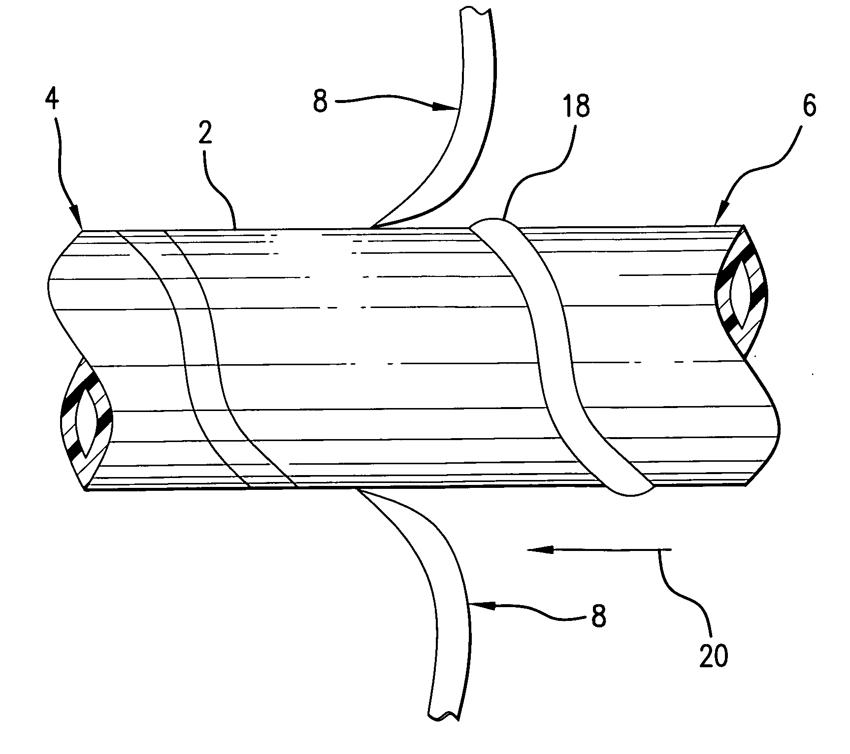
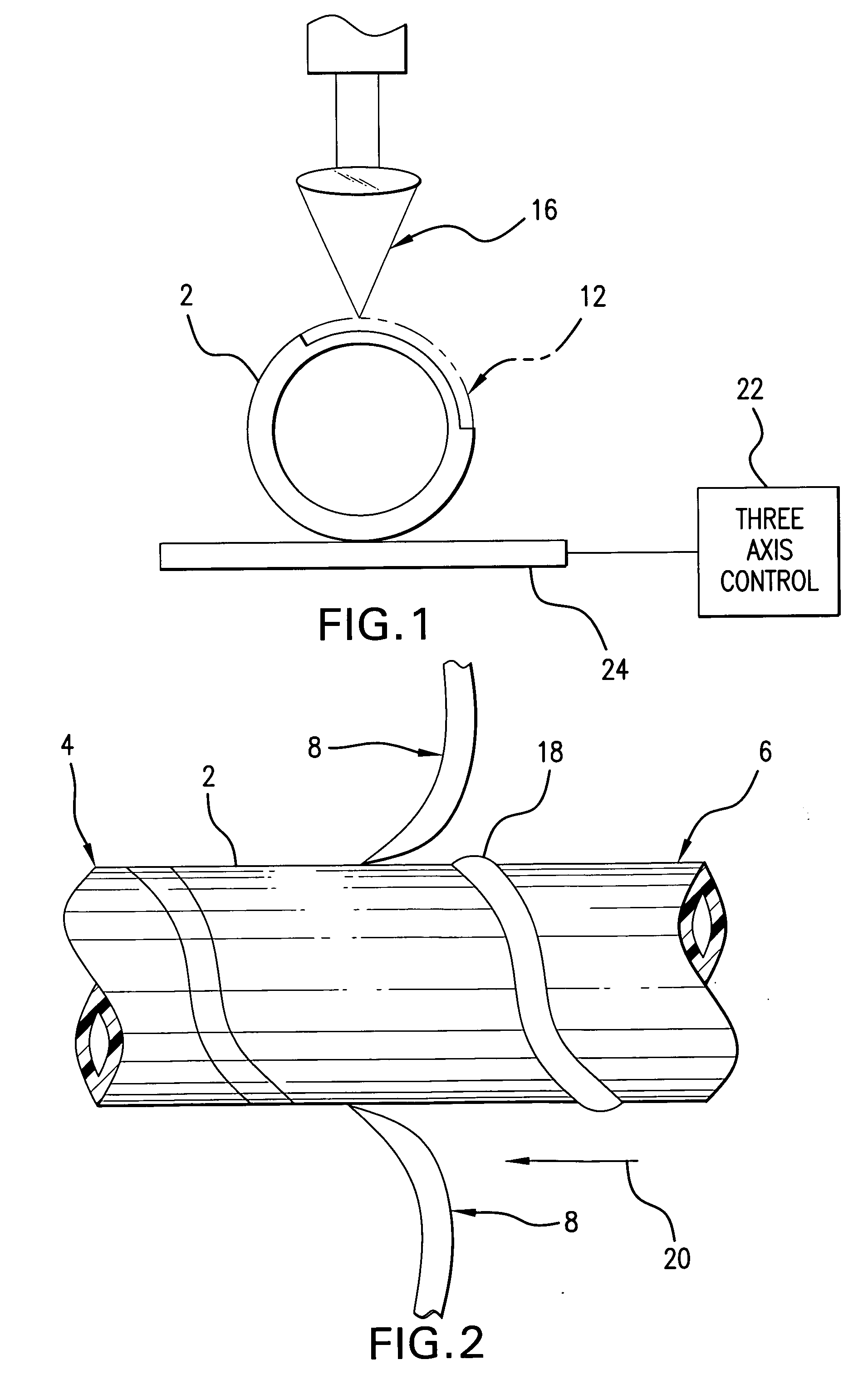
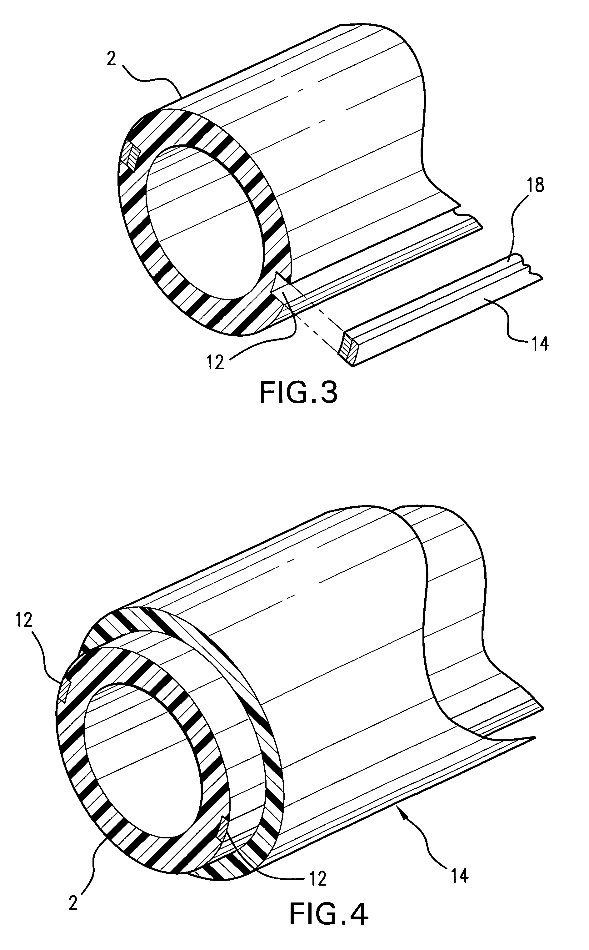
[0024]Referring to FIGS. 1-7, there is shown an electrically conductive polymer tube 2 that is coupled to electrical devices and a method for forming electrically conductive patterns to provide an electrically conductive path on the polymer tube 2. The polymer tube 2 may be any type of well-known type of polymer tube 2, such as, a catheter. Preferably, the polymer tube 2 is of the type used in medical procedures, specifically for use within the human body.

[0025]The polymer tube 2 is adapted to be coupled to electrical devices. There are many instances during medical procedures that devices requiring electrical energy are used. One example of an electrical device is a video camera. Supplying power to a video camera through a polymer tube with electrically conductive paths, 2, such as a catheter, minimizes the need for various devices that are electrically conductive by incorporating as much into the polymer tube 2. The polymer tube 2 has a proximal end 4 and a distal end 6. One of ei...


PUM

PropertyMeasurementUnit
temperaturesaaaaaaaaaa
diameteraaaaaaaaaa
wavelengthsaaaaaaaaaa

Abstract

A method for forming electrically conductive patterns to provide an electrically conductive path on a polymer tube is provided. The method includes the steps of establishing a polymer tube and mounting such in a displaceable and rotatable mounting that is adapted to provide both axial and rotational motion. This is followed by forming at least one channel having a predetermined pattern in the polymer tube with a focused energy beam, the channel then being filled with an electrically conductive paste or electrically conductive slurry material. The polymer tube is then heated to temperatures less than 250° C. to cure the electrically conductive paste or electrically conductive slurry material. The electrically conductive paste or electrically conductive slurry material is then covered with a polymer layer.

Description

BACKGROUND OF THE INVENTION[0001]1. Field of the Invention[0002]The subject invention relates to a polymer tube with embedded electrical conductors, such as a medical catheter, adapted to be coupled with one or more electrical devices. Polymer tubes, such as catheters, are used in a variety of medical procedures. Embedded electrical conductors and electrically conductive sections are needed in several types of plastic catheters, such as those carrying electrical sensors or sensing electrodes. Conductor patterns of this type are used to transmit electrical signals along the length of the catheter and to connect sensors at ends of the catheter to electrical power and communication circuitry. These same conductor patterns may also exhibit radio-opacity and enhance diagnostic imaging of regions of the catheter in which they are embedded.[0003]This invention is directed to medical apparatuses included catheters. This invention is further directed to systems and methods for electrically c...

Claims


Application Information

Patent Timeline
Patent Type & Authority Applications(United States)
IPC IPC(8): A61M25/098A61L33/00
CPCA61L29/085A61L29/14A61M25/0009A61M25/0013H05K1/0284H05K3/0032Y10T29/49155H05K3/1258H05K2201/09018Y10T29/49117Y10T29/49156Y10T428/24917H05K3/107
Inventor BEER, LAWRENCE P.ADELSTEIN, MICHAELCHRISTENSEN, C. PAUL
Owner POTOMAC PHOTONICS
Why Eureka
Try Eureka