Numerical control system

a control system and numerical control technology, applied in the field of numerical control systems, can solve problems such as increased processing time, system malfunction detection, and abnormalities, and achieve the effect of improving safety

Active Publication Date: 2008-05-29
MITSUBISHI ELECTRIC CORP
View PDF1 Cites 10 Cited by
  • Summary
  • Abstract
  • Description
  • Claims
  • Application Information

AI Technical Summary

Benefits of technology

[0011]In view of the above, the object of the present invention is to provide a numerical control system that is capable of improving safety when a plurality of systems individually operating in asynchronization with one another are operated as a single control unit.

Problems solved by technology

In the above-mentioned first patent document, a control unit for controlling the machine and a operation panel arranged outside of the control unit are electrically connected to each other, and if a processing request issued from the control unit is not received by the operation panel, it is assumed that abnormality occurs.
However, in the numerical control apparatus as described in the above-mentioned first patent document, whether the operation panel receives a signal is only used as a criterion for determination, so there is a problem that only a system malfunction can be determined.
In addition, in the above-mentioned numerical control system as described in the second patent document, the more precisely a real machine is tried to be expressed so as to perform collision detection with high accuracy by using three-dimensional shapes, the more processing time is required, and in that case, there will be a problem of inducing a system malfunction.
Further, if the system falls into a state in which a lot of processing time for collision detection is required in case where a tool and a material are in contact with each other, there is a problem that a work to be processed might be damaged or the tool might be broken.

Method used


Image

  • Numerical control system
  • Numerical control system
  • Numerical control system

Examples


embodiment 1

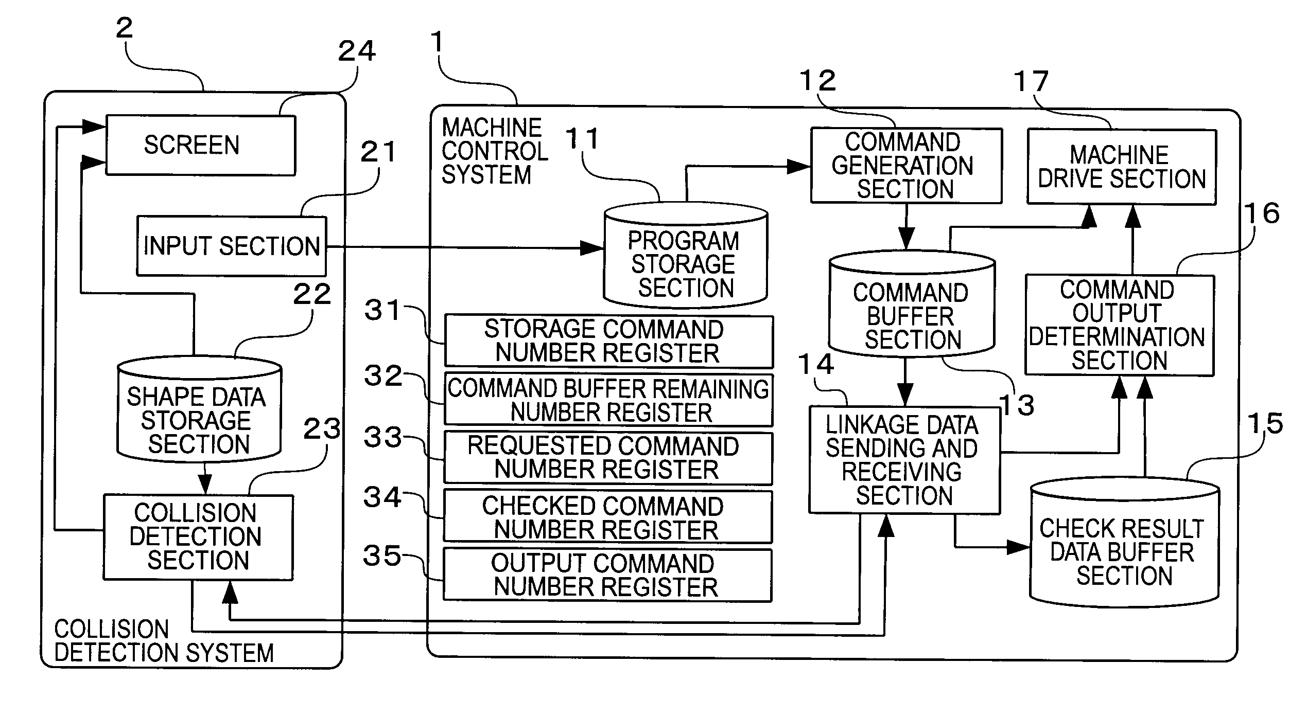
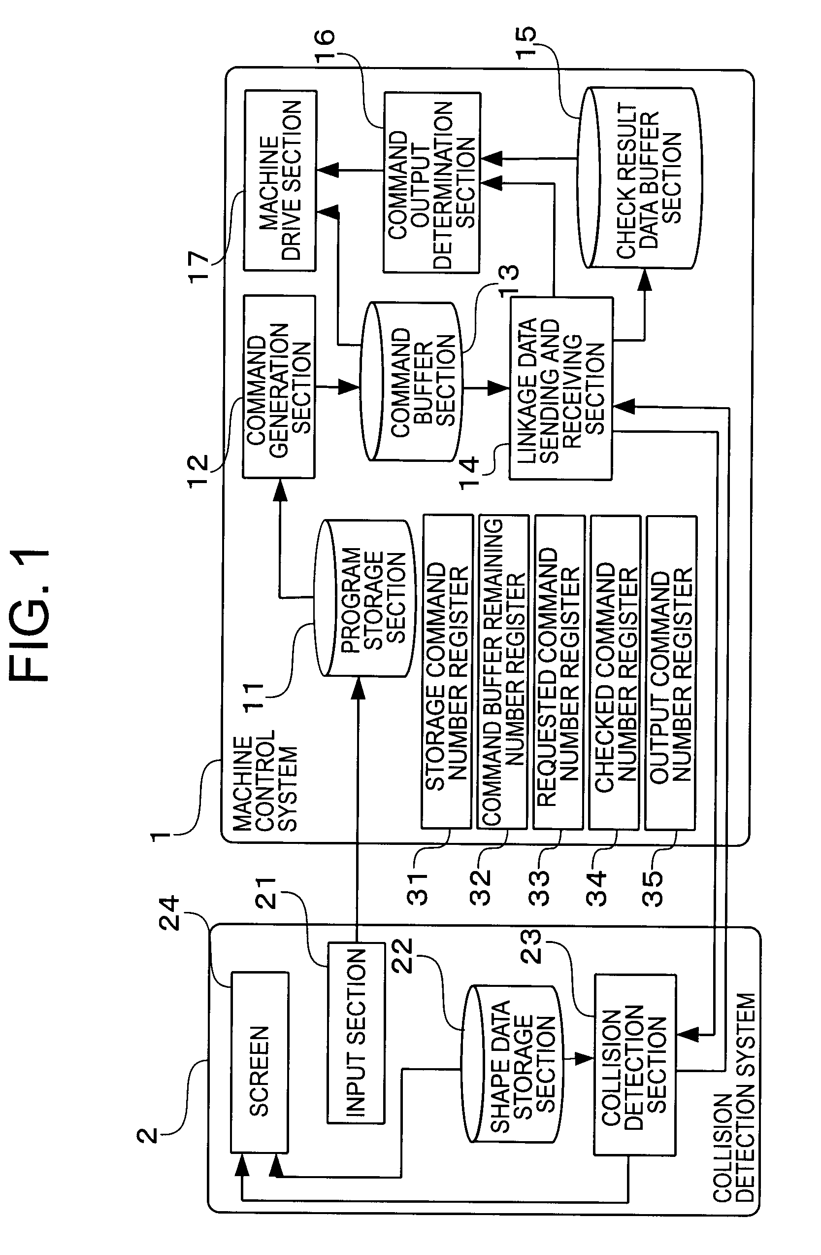
[0028]Referring to the drawings and first to FIG. 1, there is shown, in a block diagram, the configuration of a numerical control system according to a first embodiment of the present invention.

[0029]The numerical control system according to the first embodiment of the present invention is provided with a machine control system 1 that controls a machine at a prescribed period or cycle and a collision detection system 2 that operates in a period different from that of the machine control system 1 or in a constantly changing period, wherein the machine control system 1 and the collision detection system 2 operate in association with each other.

[0030]The machine control system 1 has a program storage section 11, a command generation section 12, a command buffer section 13, a linkage data sending and receiving section 14, a check result data buffer section 15, a command output determination section 16, and a machine drive section 17.

[0031]In addition, the machine control system 1 furthe...

embodiment 2

[0092]FIG. 10 is a block diagram of a machine control system according to a second embodiment of the present invention.

[0093]A numerical control system according to the second embodiment of the present invention is different from the numerical control system according to the first embodiment in a machine control system 1B, but is the same in other respects as that of the first embodiment with the like parts or elements being identified by the same reference numerals and characters while omitting an explanation thereof, as shown in FIG. 10.

[0094]The machine control system 1B according to this second embodiment is different from the machine control system 1 of the first embodiment in a command generation section 12B and a command output determination section 16B, but is the same in other respects as that of the machine control system 1, and hence like components or parts are identified by like reference numerals and characters while omitting a detailed explanation thereof. The command...

embodiment 3

[0108]A numerical control system according to a third embodiment of the present invention is different from the numerical control system according to the first embodiment in a collision detection system, but is the same in other respects as that of the first embodiment with the like parts or elements being identified by the same reference numerals and characters while omitting an explanation thereof. The collision detection system according to the third embodiment is different from the collision detection system 2 according to the first embodiment in one aspect of operation after the detection of a collision, but is the same in other aspects of operation as that of the first embodiment.

[0109]Now, the collision detection section 23 is in a state in which by checking a check request command received from the linkage data sending and receiving section 14, it has determined that there is a probability of collision, and has returned check result data thereof to the linkage data sending a...


PUM


Abstract

A numerical control system improves safety when asynchronously operating systems are operated as a single control unit. A machine control system outputs a command generated by interpreting a program with a command number assigned thereto, sends it to a collision detection system, and receives check result data therefrom, whereby when the number of commands for which check result data are obtained is more than or equal to a preset second threshold, a command number assigned to the check result data is output when it is determined that there is no probability of collision. When the result of a check on the probability of collision for a command received from a linkage data sending and receiving section is returned, the collision detection system returns check result data to the linkage data sending and receiving section by assigning a command number given to the checked command to the check result data.

Description

BACKGROUND OF THE INVENTION[0001]1. Field of the Invention[0002]The present invention relates to a numerical control system comprising a plurality of systems having their control periods different from one another.[0003]2. Description of the Related Art[0004]As a numerical control apparatus in recent years, there is one which includes a control system for controlling a machine as a main function of the numerical control apparatus, and an operating system for providing an input / output function to produce programs, to set parameters, and to set tool data for operation of a machine tool, wherein these systems function in association with each other as a numerical control system (see, for example, a first patent document: Japanese patent application laid-open No. 2002-108423).[0005]In such a numerical control system, data transfer (sending and receiving) is carried out between the two systems. In the above-mentioned first patent document, a control unit for controlling the machine and a...

Claims


Application Information

Patent Timeline
Patent Type & Authority Applications(United States)
IPC IPC(8): G05B19/18G05B19/414
CPCG05B19/408G05B19/4061
Inventor TAKAHASHI, NOBUYUKINIGAZAWA, HIROMICHIKAMIYA, TAKASHI
Owner MITSUBISHI ELECTRIC CORP
Why Eureka
Try Eureka