
Industrial Robot System

a robot and robot technology, applied in the field of industrial robot systems, can solve the problems of inability to move the robot with the tpu, inability to operate the robot by means of the tpu, and failure to check safety equipment and find faultless

Active Publication Date: 2008-05-29
ABB (SCHWEIZ) AG
View PDF10 Cites 45 Cited by
  • Summary
  • Abstract
  • Description
  • Claims
  • Application Information

AI Technical Summary

Benefits of technology

[0013]The object of the present invention is to provide an improved solution to the problem regarding how to couple a wireless TPU to a specific robot. More specifically, the object of the present invention is to provide a solution, which is advantageous to use when the same TPU is used for controlling more than one robot.

Problems solved by technology

When the enabling device is released it is not possible to operate the robot by means of the TPU.
When the enabling function is deactivated, it is not possible to move the robot with the TPU, even with the enabling button pressed.
Before connecting the TPU to the safety system, the safety equipment has to be checked and found faultless.
Otherwise, there is a risk for personal injury, should the operator believe that he is operating a certain robot but is instead operating another robot in the cell.
In manual mode the enabling function is activated and it is possible to move the robot with the control devices of the TPU, i.e. to manually jog the robot by means of the TPU, and in automatic mode the enabling function is deactivated and it is not possible manually jog the robot by means of the TPU.
However, there are some drawbacks with this solution, for example the operator may find it troublesome to move the key device between the robot and the TPU, or the key device may be lost.
Thus, a problem in connection with using the same TPU for controlling more than one robot is that it is time-consuming and troublesome for the operator to change between the robots to be controlled by the TPU.

Method used


Image

  • Industrial Robot System
  • Industrial Robot System
  • Industrial Robot System

Examples


Embodiment Construction

[0040]FIG. 1 shows an industrial robot system comprising an industrial robot 1, including the manipulator 2, a control unit 3 for controlling the manipulator, and a portable operator control device 4, in the following denoted a TPU (Teach Pendant Unit) for teaching and manually operating the manipulator. The TPU is communicating with the control unit 3 via a wireless data link 5.

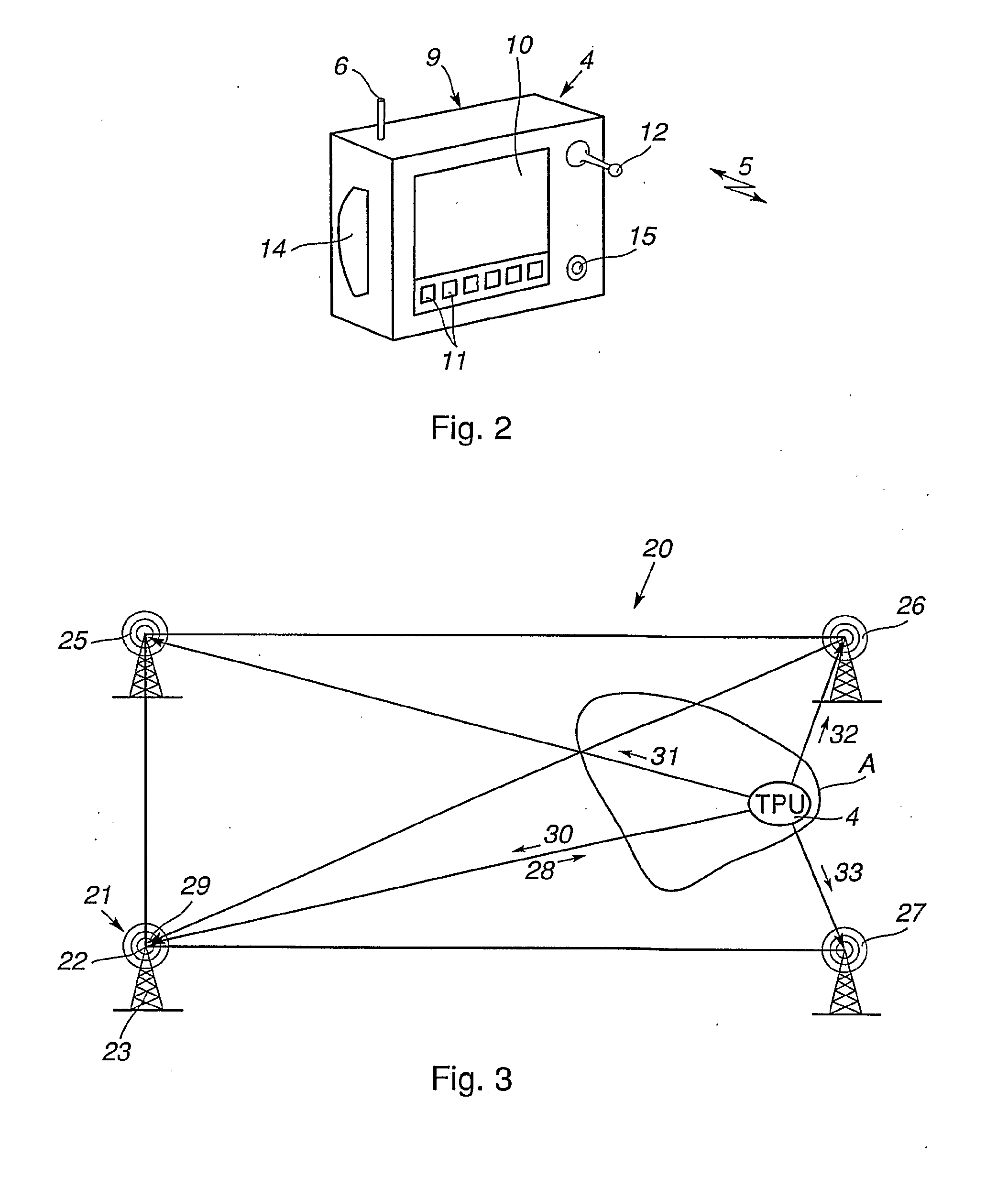
[0041]FIG. 2 shows the TPU in more detail. The TPU comprises a portable box 9 including a display screen 10, function keys 11, a joystick 12, an enabling device 14 and an emergency stop device 15. The TPU also includes and antenna 6 for wireless communication with the control unit 3. The function keys 11 permit the operator to select various states for the control system. The joystick 12 is used for controlling the movement of the manipulator when the robot is manually operated. The enabling device 14 comprises a button, which has to be pressed down by the operator to enable control of the robot by the TPU. ...


PUM


Abstract

An industrial robot system including at least one industrial robot including a manipulator and a control unit for controlling the manipulator, a portable operator control device for teaching and manually operating a robot. The portable operator control device includes safety equipment including an enabling device, which upon activation enables manual operation of the robot by the portable operator control device. The portable operator control device is adapted for wireless communication with the control unit, and a detecting unit that detects when the portable operator control device enters an area defined in the vicinity of the manipulator. The robot includes an enabling function which upon activation enables the enabling device of the portable operator control device, and upon deactivation disables the enabling device. The robot system is adapted to automatically activate the enabling function of the robot upon detecting that the portable operator control device enters the defined area.

Description

CROSS-REFERENCE TO RELATED APPLICATIONS[0001]This application claims priority to U.S. provisional patent application No. 60 / 625,285 filed 4 Nov. 2004 and Swedish patent application number 0402696-9 filed 4 Nov. 2004 and is the national phase under 35 U.S.C. § 371 of PCT / SE2005 / 001577 filed 21 Oct. 2005.FIELD OF THE INVENTION[0002]The present invention relates to an industrial robot system including at least one industrial robot comprising one or more manipulators, and a control unit for controlling the manipulators, and a portable operator control device, which comprises safety equipment including an enabling function comprising an enabling device, which upon activation enables manual operation of the robot by means of the TPU. The invention also relates to a method for coupling the TPU to the industrial robot. A manipulator is a mechanical unit movable about at least on axis. A manipulator could be a conveyer belt as well as a 6-axis robot.PRIOR ART[0003]An industrial robot is prog...

Claims


Application Information

Patent Timeline
Patent Type & Authority Applications(United States)
IPC IPC(8): G05B19/414G05B19/048B25J9/00B25J
CPCB25J9/1674B25J13/06B25J19/06G01S5/14G05B2219/40202G05B2219/33008G05B2219/36162G05B2219/39447G01S13/878
Inventor SJOBERG, RALPH
Owner ABB (SCHWEIZ) AG
Features
  • Generate Ideas
  • Intellectual Property
  • Life Sciences
  • Materials
  • Tech Scout
  • Unparalleled Data Quality
  • Higher Quality Content
  • 60% Fewer Hallucinations
Learn More