
Process for making software diagnostics more efficient by leveraging existing content, human filtering and automated diagnostic tools

a software diagnostic and content technology, applied in the field of software tools, can solve problems such as difficulty in setting such a breakpoint, inability to reproduce conditions, and bugs giving rise to actual errors

Inactive Publication Date: 2008-05-29
SOURCELABS
View PDF25 Cites 14 Cited by
  • Summary
  • Abstract
  • Description
  • Claims
  • Application Information

AI Technical Summary

Benefits of technology

[0014]Another object of the present invention is to provide improved methods of software diagnostics by gathering and digesting information down to the most important nuggets and bugs to help customers preventatively avoid problems.
[0015]Yet another object of the present invention is to provide improved methods of software diagnostics by using probes that can pull information from a running process and help it match against the information gathered as well as information created.
[0017]Another object of the present invention is to provide improved methods of software diagnostics where items from machine data are extracted from human data to be operated on to produce digested data as feeds.

Problems solved by technology

Two significant problems arise in using this model.
Setting such a breakpoint can be difficult when working with an event-driven system (such as the Microsoft Windows.RTM. operating system), because the developer does not always know which of the event handlers (callbacks) will be called.
The second problem is that some bugs give rise to actual errors only during specific execution conditions, and these conditions cannot always be reproduced during the debugging process.
For example, a program error that occurs during normal execution may not occur during execution under the debugger, since the debugger affects the execution of the program.
An example of this second type of problem is commonly encountered when software developers attempt to diagnose problems that have been identified by customers and other end users.
Quite often, software problems appear for the first time at a customer's site.
When trying to debug these problems at the development site (typically in response to a bug report), the developer often discovers that the problem cannot be reproduced.
Distributed, client / server, and parallel systems, especially multi-threaded and multi-process systems, are notorious for having non-reproducible problems because these systems depend heavily on timing and synchronization sequences that cannot easily be duplicated.
When a bug cannot be reproduced at the development site, the developer normally cannot use a debugger, and generally must resort to the tedious, and often unsuccessful, task of manually analyzing the source code.
Unfortunately, sending a developer to a customer's site is often prohibitively time consuming and expensive, and the process of setting up a debugging environment (source code files, compiler, debugger, etc.) at the customer site can be burdensome to the customer.
Unfortunately, the imbedded code solution depends on inserting the tracing code into the source prior to compiling and linking the shipped version of the application.
Trying to anticipate where a bug will occur is, in general, a futile task.
Often there is no imbedded code where it is needed, and once the application has been shipped it is too late to add the desired code.
Another drawback of current monitoring systems is the inability to correctly handle parallel execution, such as in a multiprocessor system.
Using serial techniques for parallel systems may cause several problems.
First, the sampling activity done in the various parallel entities (threads or processes) may interfere with each other (e.g., the trace data produced by one entity may be over written by another entity).
Second, the systems used to analyze the trace data cannot assume that the trace is sequential.
Displaying the trace data as a separate calling tree for each entity is not appropriate, as this does not reveal when, during the execution, contexts switches were done between the various parallel entities.

Method used


Image

  • Process for making software diagnostics more efficient by leveraging existing content, human filtering and automated diagnostic tools
  • Process for making software diagnostics more efficient by leveraging existing content, human filtering and automated diagnostic tools
  • Process for making software diagnostics more efficient by leveraging existing content, human filtering and automated diagnostic tools

Examples


Embodiment Construction

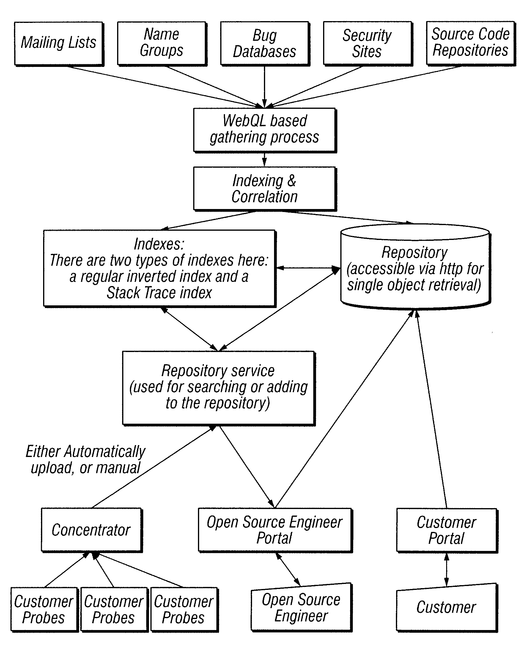
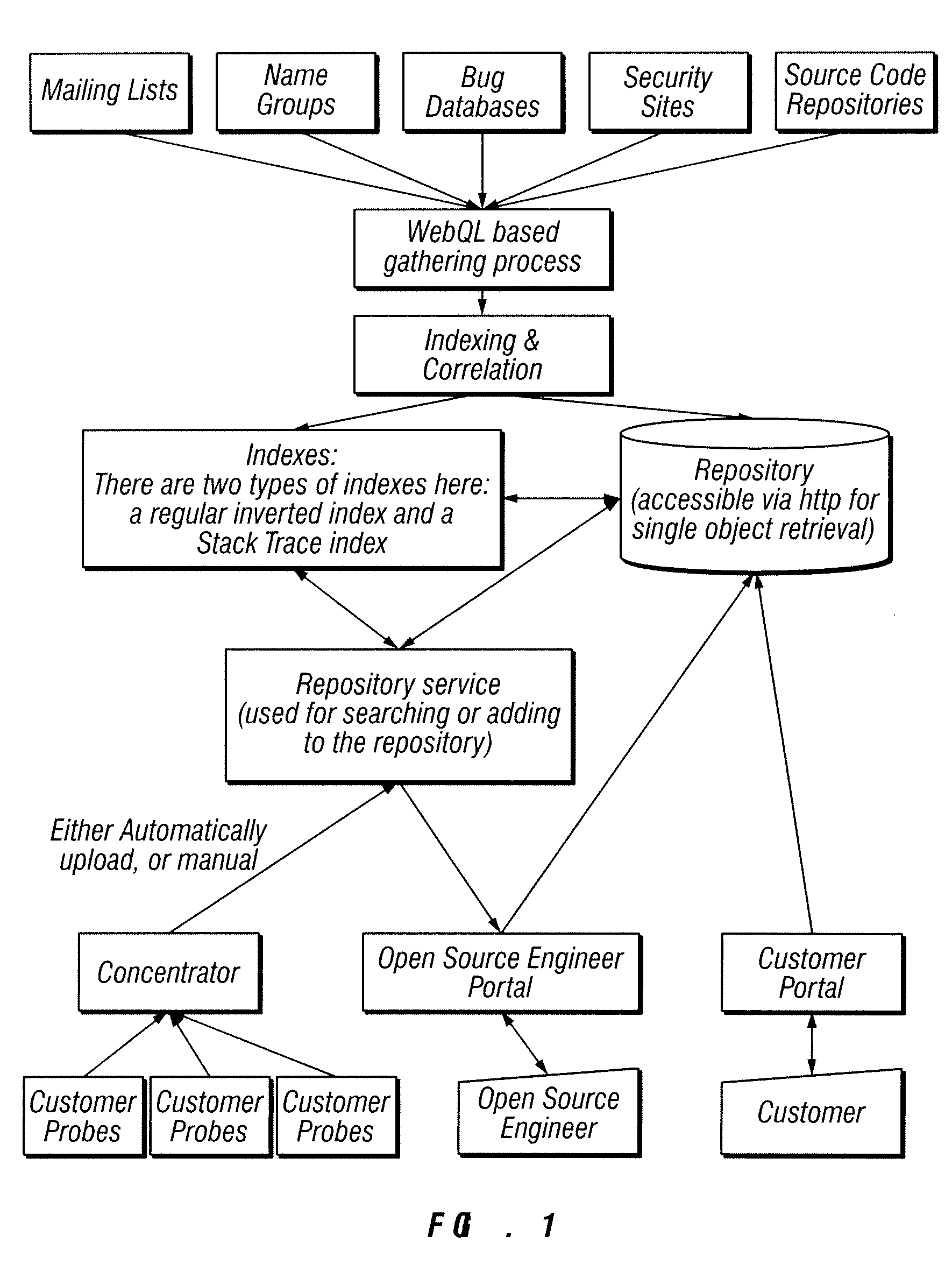
[0029]In one embodiment of the present invention, illustrated in FIG. 1, the methods and systems of the present invention make software diagnostics more efficient. This can be achieved by, (i) gathering information and digest it down to the most important nuggets and bugs to help customers preventatively avoid problems, and (ii) use probes that can pull information from a running process and help it match against the information gathered as well as information created.

[0030]There are three important parts of the information gathering process. In one embodiment, data is pulled from external data Sources. In one embodiment of the present invention raw data is filtered through a mix of automatic and manual processes. One embodiment of the present invention also opens up manual filtering on non-bug content by allowing tagging and annotations to be added on any content similar to the way the meta data is added to bug content.

[0031]A feedback loop can be used to provide the filtering. Add...


PUM


Abstract

Improved methods of software diagnostics are provided. Searches of data sources are conducted using search terms from internal computer information to obtain searched data. The searched data is processed by extracting technical features. The technical features are indexed to create indexes that can be searched via machine state. Filtering is conducted over the gathered data to create feeds that are available to customers. Stack traces are extracted for the purpose of matching and researching using machine state rather than key words.

Description

CROSS-REFERENCE TO RELATED APPLICATIONS[0001]This application claims the benefit of U.S. Ser. No. 60 / 816,797, filed Jun. 26, 2006, which application is fully incorporated herein by reference.BACKGROUND[0002]1. Field of the Invention[0003]The present invention relates to software tools for assisting software developers in the task of monitoring and analyzing the execution of computer programs, such as during the debugging process.[0004]2. Description of the Related Art[0005]Despite the significant diversity in software tracing and debugging programs (“debuggers”), virtually all debuggers share a common operational model: the developer notices the presence of a bug during normal execution, and then uses the debugger to examine the program's behavior. The second part of this process is usually accomplished by setting a breakpoint near a possibly flawed section of code, and upon reaching the breakpoint, single-stepping forward through the section of code to evaluate the cause of the pro...

Claims


Application Information

Patent Timeline
Patent Type & Authority Applications(United States)
IPC IPC(8): G06F17/30
CPCG06F11/36
Inventor PUGH, WILLIAMSWEET, RYANJACOBSON, STEVEHANSSON, CHRISTIANJEKEL, ROSS ARDENRUAN, YONGSHAO
Owner SOURCELABS
Learn More