Carbon dioxide capture systems and methods

a carbon dioxide and carbon dioxide technology, applied in the field of carbon dioxide capture, can solve the problems of high cost of carbon dioxide capture using current technology, high cost of cosub>2 /sub>capture, etc., and achieve the effect of convenient co2 separation and capture from power plants and more cost effectiv

Inactive Publication Date: 2008-06-05
GENERAL ELECTRIC CO
View PDF11 Cites 206 Cited by
  • Summary
  • Abstract
  • Description
  • Claims
  • Application Information

AI Technical Summary

Benefits of technology

[0006]Accordingly, there is a need for a new CO2 separation system and method to

Problems solved by technology

Existing CO2 capture technologies, however, are not cost-effective when considered in the context of sequestering CO2 from power plants.
The cost of CO2 capture using current technology, however, can be as high as $150 per ton—m

Method used


Image

  • Carbon dioxide capture systems and methods
  • Carbon dioxide capture systems and methods
  • Carbon dioxide capture systems and methods

Examples


Embodiment Construction

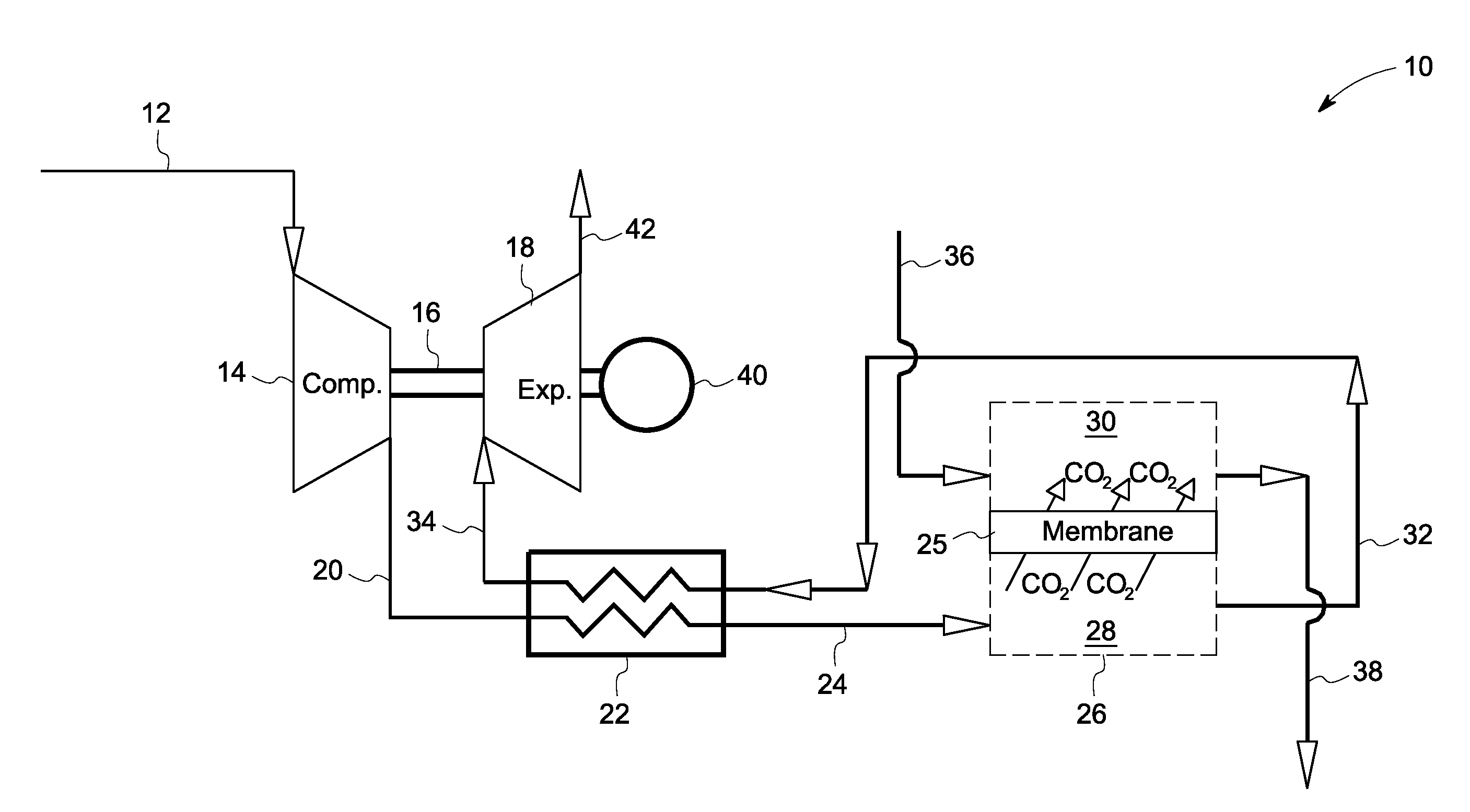
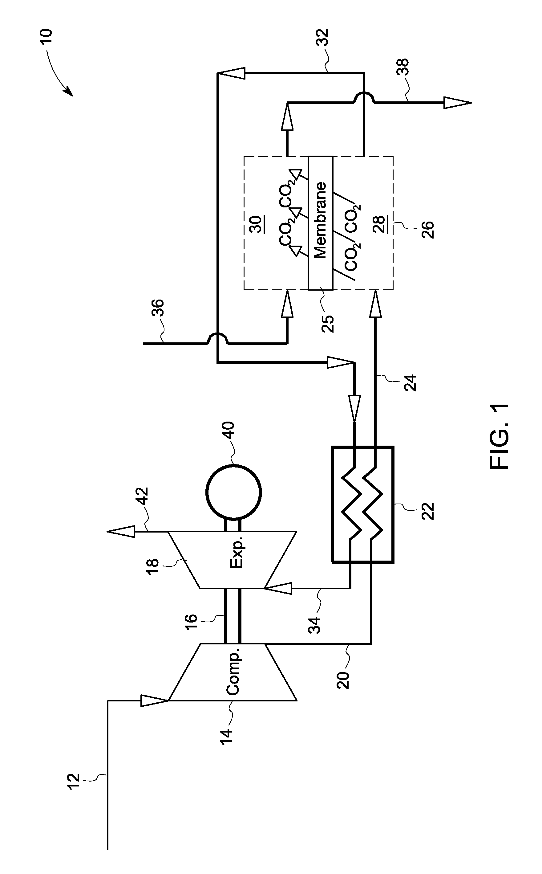
[0017]FIG. 1 illustrates a carbon dioxide (CO2) separation system 10 including a compressor 14 for receiving an exhaust gas 12 comprising CO2 and generating a compressed exhaust gas 20. The separation system 10 also includes a separator 26 configured to receive the compressed exhaust gas 20 and generate a CO2 lean stream 32. The separator 26 includes a first flow path 28 for receiving the compressed exhaust gas 20, a second flow path 30 for directing a sweep fluid 36 therethrough, and a material 25 with selective permeability of carbon dioxide for separating the first and the second flow paths 28 and 30 and for promoting carbon dioxide transport therebetween. The CO2 separation system 10 further includes an expander 18 optionally coupled to the compressor 14 through a common shaft 16 for receiving and expanding the CO2 lean stream 32 to generate power through generator 40 and an expanded CO2 lean stream 42, or reduce the overall power requirement in the compressor-expander section t...


PUM


Abstract

A carbon dioxide separation system includes a compressor for receiving an exhaust gas comprising CO2 and generate a compressed exhaust gas and a separator configured to receive the compressed exhaust gas and generate a CO2 lean stream. The separator includes a first flow path for receiving the compressed exhaust gas, a second flow path for directing a sweep fluid therethrough, and a material with selective permeability of carbon dioxide for separating the first and the second flow paths and for promoting carbon dioxide transport therebetween. The system further includes an expander coupled to the compressor for receiving and expanding the CO2 lean stream to generate power and an expanded CO2 lean stream.

Description

CROSS REFERENCE TO RELATED APPLICATIONS[0001]This application is a Continuation-In-Part of U.S. patent application Ser. No. 11 / 564,912, Docket Number 207795-1, entitled “CARBON DIOXIDE CAPTURE SYSTEMS AND METHODS,” filed Nov. 30, 2006, which application is herein incorporated by reference.BACKGROUND[0002]This invention relates generally to carbon capture and more specifically to methods and systems for capturing carbon dioxide.[0003]Before carbon dioxide (CO2) gas can be sequestered from power plants and other point sources, it must be captured in a relatively pure form. On a mass basis, CO2 is the nineteenth largest commodity chemical in the United States, and CO2 is routinely separated and captured as a byproduct of industrial processes such as synthetic ammonia production, hydrogen (H2) production or limestone calcination.[0004]Existing CO2 capture technologies, however, are not cost-effective when considered in the context of sequestering CO2 from power plants. Most power plants...

Claims


Application Information

Patent Timeline
IPC IPC(8): F01N3/00
CPCB01D53/22B01D53/62B01D2257/504F02C1/02Y02C10/10F23J15/02F23J2215/50Y02C10/04F02C1/04Y02E20/32Y02A50/20Y02C20/40
Inventor FINKENRATH, MATTHIASBARTLETT, MICHAEL ADAMHOFFMANN, STEPHANIE MARIE-NOELLERUUD, JAMES ANTHONY
Owner GENERAL ELECTRIC CO
Why Eureka
Try Eureka