Downhole power source

a power source and downhole technology, applied in the field of hydrocarbon production, can solve the problems of lithium batteries being easily exploding, lithium batteries can be quite expensive, and the batteries made from lithium batteries are not rechargeabl

Inactive Publication Date: 2008-06-05
BAKER HUGHES INC
View PDF7 Cites 61 Cited by
  • Summary
  • Abstract
  • Description
  • Claims
  • Application Information

AI Technical Summary

Problems solved by technology

However each of these devices suffers from one of more of the following drawbacks.
Often the temperatures downhole can exceed over 100° C. Thus a limited number of batteries are applicable for such use, for example lithium has been found to be a useful battery component.
However lithium can be toxic and lithium batteries also are susceptible to exploding.
Furthermore, batteries made from lithium can be quite expensive and they are not rechargeable.
With regard to wireline supplied power downhole, additional limitations exist by using this as an electrical source.
For example, the diameter of the wireline is limited due to weight constraints, which limits the amount of electrical current that can flow through the wireline.
This further limits the amount of current that can reasonably be transmitted along the wireline.
An additional limitation of wireline is that it is used in conjunction with some sort of wireline tool, such as an acoustic or perforating device.
Thus with regard to devices involved in reservoir management, such the sensors and valving described above, a wireline source of electrical current would be inappropriate.
These devices tend to be somewhat bulky thereby consuming a large amount of space when disposed within the wellbore.
Moreover, since these devices require the flow of fluid, they are not operative without a substantial amount of fluid flow within the wellbore.
Since there are periods of time with limited or no flow through the wellbore, these devices are limited in the time that they may be able to operate.
Additionally, since these require the flow of fluid they necessarily produce a pressure drop of wellbore fluid flow, which has other undesirable affects during exploration and / or production.

Method used


Image

  • Downhole power source
  • Downhole power source
  • Downhole power source

Examples


Embodiment Construction

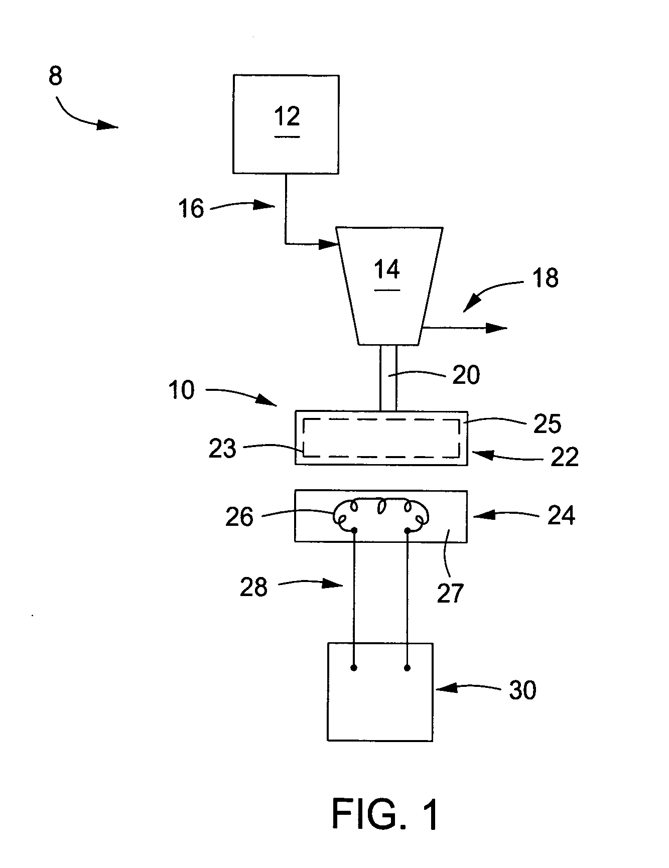
[0014]The device and apparatus that is the subject of the present disclosure is a system for the generation of power for use downhole. One embodiment of a downhole power source 8 in accordance with the present disclosure is shown in schematically view in FIG. 1. The downhole power source 8 is comprised of a microgenerator 10 in communication with a motive gas source 12. The microgenerator 10 further comprises a rotor 22 that is in electromagnetic communication with a stator 24, wherein the electromagnetic communication is capable of producing an electrical current for powering a load 30.

[0015]As shown in this embodiment the microgenerator 10 comprises a rotational activation system, such as a turbine 14 mechanically connected to the rotor 22 via a shaft 20. Although the embodiment of FIG. 1 is shown in a side schematical view, it should be pointed out that the rotor 22 preferably has a disc like configuration wherein the diameter of the disc exceeds its thickness. Since the rotor 22...


PUM


Abstract

A power source for use in a downhole environment. The power source can include a microgenerator, where the microgenerator is comprised of a motive source, a rotor, a stator, and an electrical load. The motive source can be compressed gas, liquid, two-phase fluid, or combustion gases. The rotor may comprise a magnet and the stator may comprise a coil, such that rotating the rotor coaxially proximate to the stator produces electrical current. The electrical load includes any device used in downhole exploration and production that requires electrical energy.

Description

BACKGROUND OF THE INVENTION[0001]1. Field of the Invention[0002]The invention relates generally to the field of hydrocarbon production. More specifically, the present invention relates to a power source for use within a wellbore.[0003]2. Description of Related Art[0004]Recent advancements in the field of oil and gas exploration and production have produced devices requiring a constant source of power. Typically, these devices are powered through a dedicated power supply that is in electrical communication with these devices. One example of a device requiring downhole power includes acoustic signal producers that are disposed downhole for identification of casing perimeters such as defects and / or location of casing collars. Other examples of energy consuming devices downhole include sensors disposed within a casing for monitoring fluid flow parameters, such as pressure, temperature, and flow rate. Additional sensors include an optical sensor, an electromagnetic energy sensor or an ac...

Claims


Application Information

Patent Timeline
Patent Type & Authority Applications(United States)
IPC IPC(8): E21B47/00
CPCE21B41/0085
Inventor GOLD, RANDY
Owner BAKER HUGHES INC
Why Eureka
Try Eureka