
Closed Loop Control Bore Hole Drilling System

Active Publication Date: 2008-06-05
HALLIBURTON ENERGY SERVICES INC
View PDF11 Cites 14 Cited by
  • Summary
  • Abstract
  • Description
  • Claims
  • Application Information

AI Technical Summary

Benefits of technology

[0035]By mechanically decoupling the sensor unit from the drilling tool, in use, the motion and vibrations generated by the drilling tool are reduced and preferably eliminated by the decoupling means. In this manner, a benign environment is provided for the sensor unit such that continuous and accurate readings may be obtained.
[0036]In a preferred embodiment the decoupling means is mechanically decoupled from the rotary motion of the drilling tool. The decoupling means therefore remains stationary, or near stationary, with respect to an Earth fixed reference frame. In this manner, the output of the sensors is improved and preferable perfected and in particular, gyroscopes may be utilised.
[0038]By utilising said decoupling means, the vibratory forces experienced by the sensor unit are considerably lower than would be experienced by the sensor unit if placed in the BHA, above the rotary steerable tool. Thus, the sensor unit is able to provide accurate measurements when drilling is in progress.
[0042]The outer housing of the rotary steerable tool is preferably stabilised and remains nominally static for much of the drilling process, turning only slowly as drilling progresses. For example, the rotary motion may be restrained by contact between a reference stabiliser, located along the outer body of the rotary steerable tool, and the wall of the bore hole. In addition, this continuous contact with the wall results in much of the shock and vibration being attenuated significantly, in comparison to the levels of motion that can normally be experienced by down-hole equipment whilst drilling is taking place. Hence, the levels of shock and vibration experienced by the inertial sensors are much attenuated which enables meaningful measurements to be obtained continuously throughout the drilling process.
[0046]The Inertial Measurement Unit (IMU) can operate without magnetometers, and preferably does not comprise magnetometers. It is thus not usually susceptible to magnetic interference. This being the case, it can be located on the rotary steerable tool. By positioning the IMU on the rotary steerable tool, the relationship between the longitudinal axis of the IMU and the longitudinal axis of the rotary steerable will be known. Indeed in preferred embodiments, the axes will be the same. Thus the relationship between the measurements taken by the IMU and the direction and / or position of the rotary steerable tool will also be known enabling accurate determination of the direction and / or position of the rotary steerable drilling tool (and thus the drill bit). In addition, by placing the IMU on the rotary steerable tool, it is located closer to the drill bit than would be the case if it were placed in the BHA (as is the case for conventional MWD survey tools) above the rotary steerable system.
[0048]The drive means may be any suitable mechanism for driving the rotary steerable tool. In particular however, the drive means may be a surface motor which is connected to the tool via the drill string. Rotary motion is transmitted from the surface, through the drill string, to the tool. Alternatively, the drive means may be a mud motor located in the Bottom Hole Assembly. The mud motor comprises an impeller which is driven by fluid which is pumped down the drill string from the surface. The rotary motion is then transmitted to the tool. Alternatively, the surface motor and mud motor may be used in combination to improve efficiency.

Problems solved by technology

However, in the oil and gas industries, the drilling environment can be particularly inhospitable.
The vibrations caused by the drilling tool make it difficult to obtain the continuous, accurate information required.
Furthermore, these problems are made worse at greater depths.
In view of these factors, closed loop control drilling systems are generally difficult to implement in the oil and gas industries.
In view of this, this document does not address the problems outlined above in relation to providing continuous and accurate results.
Although the system is designed for use in oil and gas drilling, it does not address the problems associated with obtaining continuous and accurate results.
However, there are various problems with the accuracy and latent reaction time of such a set-up.
Firstly, given that the rotary steerable tool can be more than 18 feet long, the conventional MWD survey tool is located a considerable distance from the drill bit.
Furthermore, magnetic sensors generally are difficult to operate on or near rotary steerable tools.
Furthermore, even if non-magnetic materials were used in the construction of the rotary steerable tool, the presence of large diameter steel rotating bodies can result in induced electromagnetic forces generating variable, unstable magnetic fields which preclude the use of magnetometers or result in spurious sensor data.
Magnetic interference may also result from the control or line currents within the rotary steerable tool.
In particular, the system control circuits may create unstable magnetic fields resulting in local disturbances.
Secondly, as MWD survey tools are typically located within the BHA at the lower end of the drill string, while drilling is in progress, the MWD survey tool is subjected to a high degree of vibration and rotary forces.
This makes it difficult to obtain accurate continuous survey data while drilling is in progress.
For the above reasons, MWD survey tools of the type described above are not ideal for use in closed loop control systems.
However, this sensor configuration does not provide actual azimuthal change.
For the above reasons, ABI sensors of the type described above are also not ideal for use in closed loop control systems.
However, as discussed above, non of these documents address the issues relating to obtaining continuous and accurate sensor readings during the drilling process.
Thus, no solution is provided to the problem of providing continuous and accurate results.
Neither document highlights the problems associated with the need to provide continuous and accurate results.
Thus, the above described prior art does not disclose any solutions to the problem of providing continuous and accurate sensor measurements for use in automated guidance of a drilling tool using closed loop control.
The lack of continuous, accurate information concerning the direction of the drill bit, or reference quality positional information, means that drilling operator intervention is required in order to maintain the drill bit trajectory along the pre-planned well path in such systems.

Method used


Image

  • Closed Loop Control Bore Hole Drilling System
  • Closed Loop Control Bore Hole Drilling System
  • Closed Loop Control Bore Hole Drilling System

Examples


first embodiment

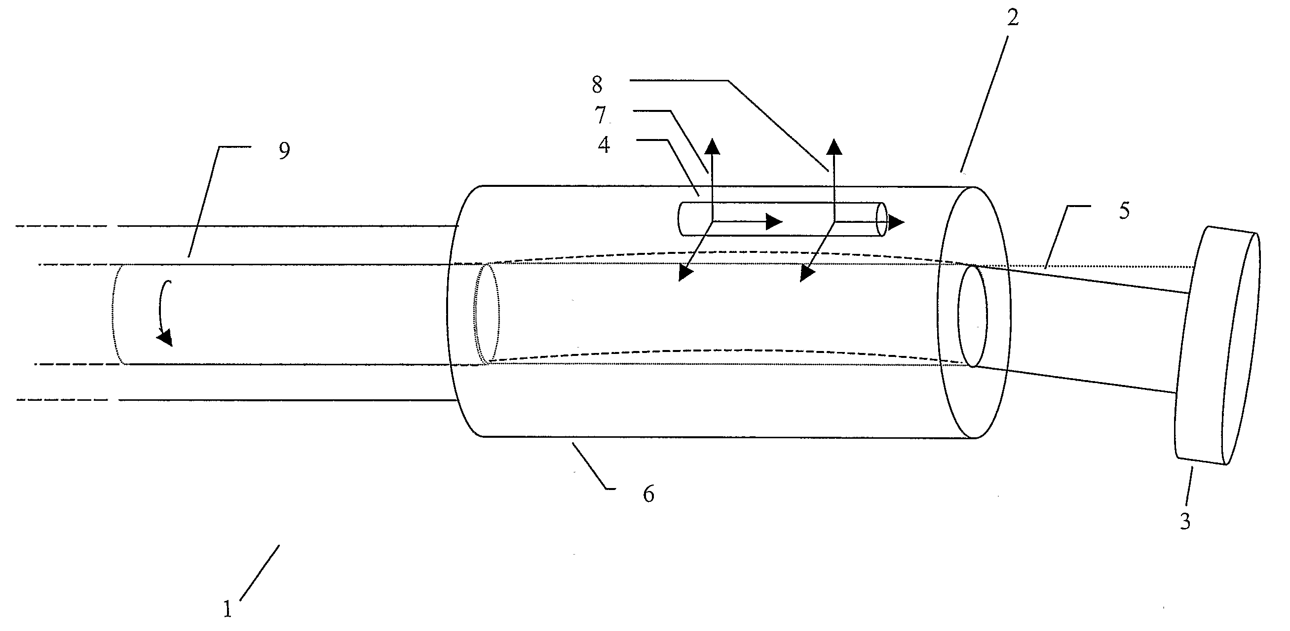
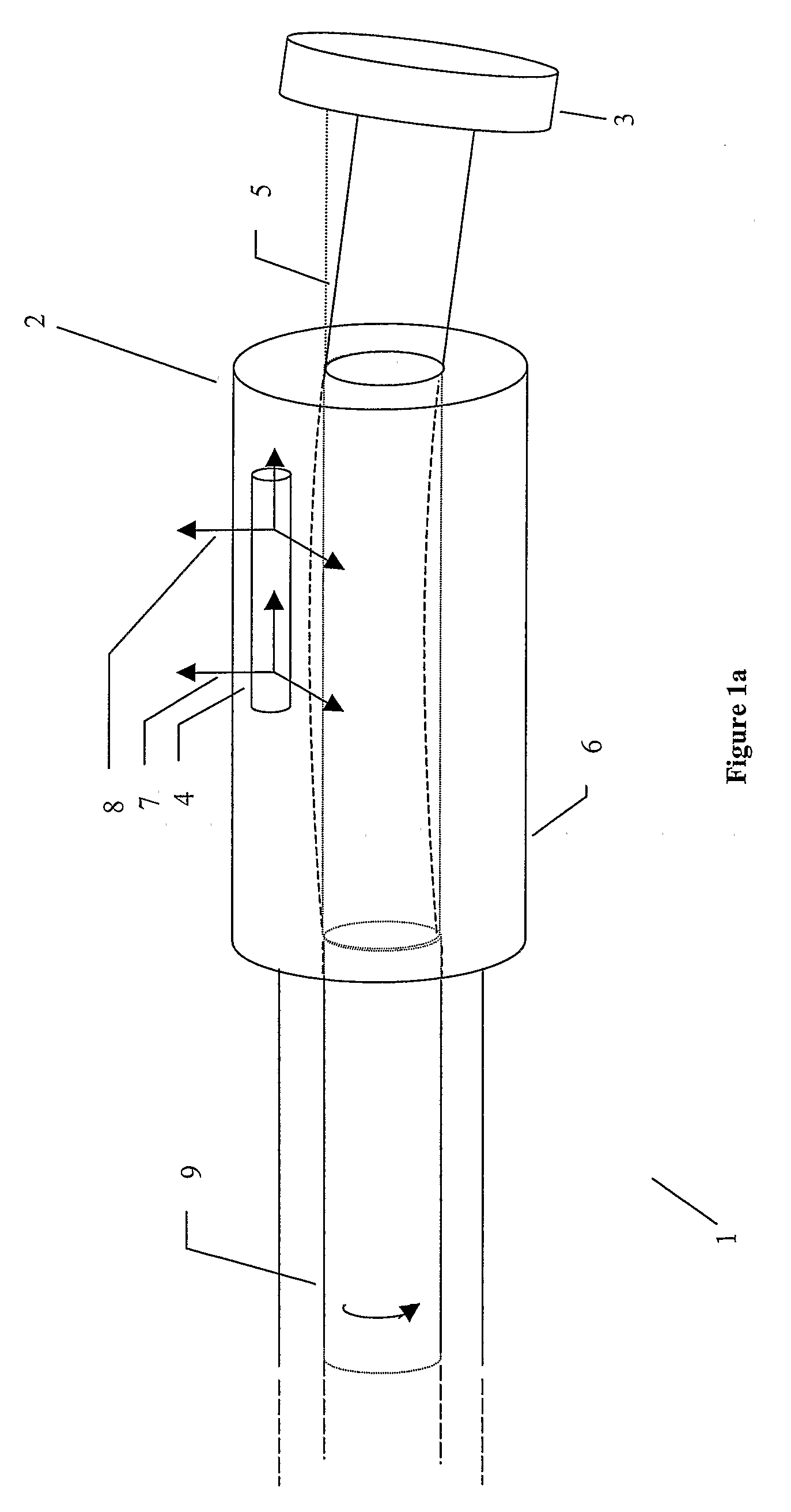
[0059]The first embodiment is shown in FIG. 1a. The sensors are positioned in the outer housing 6 of the rotary steerable tool. The outer housing remains stationary or near stationary with respect to the Earth fixed reference frame.

second embodiment

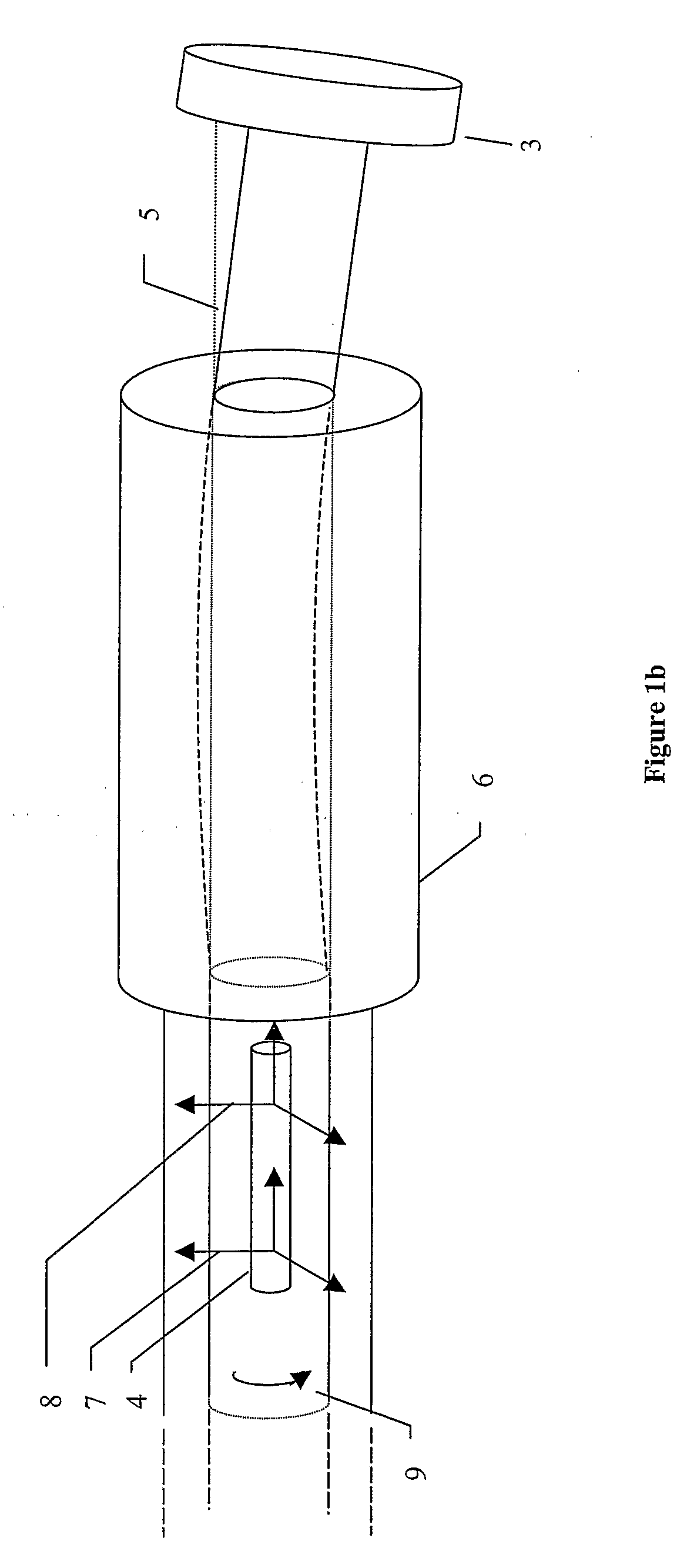
[0060]The second embodiment is shown in FIG. 1b. A rotating platform is provided in the rotating shaft 9 at the up-hole end of the drilling tool. The sensors are positioned on the rotating platform. The platform is provided with sensors which detect the rate of rotation of the rotating shaft. The platform is then caused to rotate in the opposite direction to the rotating shaft but at the same rate. In this manner, the sensors remain stationary or near stationary with respect to an Earth fixed reference frame. Thus, the sensors remain stationary or near stationary with respect to the surrounding earth.

third embodiment

[0061]The third embodiment is shown in FIG. 1c. The rotating platform of embodiment two, is positioned closer to the drill bit so that the sensor measurements more closely relate to the current drill direction / position.


PUM


Abstract

A steerable bore hole drilling tool and method of drilling bore holes. The steerable bore hole drilling tool comprise means for mechanically decoupling the sensor unit from the tool body. The method comprises a step of mechanically decoupling the sensor unit form the tool body.

Description

CROSS-REFERENCE TO RELATED APPLICATIONS[0001]This application is a National Phase entry of PCT Application No. PCT / GB2005 / 002668 filed 6 Jul. 2005 which claims priority to British Application No. 0415453.0 filed 9 Jul. 2004, both of which are incorporated herein by reference.STATEMENT REGARDING FEDERALLY SPONSORED RESEARCH OR DEVELOPMENT[0002]Not applicable.[0003]The present invention relates to a tool and method for the closed loop control of the trajectory of a steerable drilling tool during the drilling of a bore hole.BACKGROUND OF THE INVENTION[0004]The extraction of oil and gas from reserves situated below the Earth's surface involves the drilling of bore holes from the surface to the reserves. Typically, a drilling tool with a drill bit attached to its lower end is used to drill such holes. The upper end of the drilling tool attached to a drill string or drill pipe, which is attached to a drive assembly at the surface. The drive assembly causes the drilling pipe to rotate whic...

Claims


Application Information

Patent Timeline
IPC IPC(8): E21B7/04E21B47/02
CPCE21B7/04E21B7/06
Inventor WESTON, JOHN LIONELMCROBBIE, DAVID PHILIP
Owner HALLIBURTON ENERGY SERVICES INC
Learn More