Double-Wall Structure

Inactive Publication Date: 2008-06-05
KOBE STEEL LTD
View PDF14 Cites 27 Cited by
  • Summary
  • Abstract
  • Description
  • Claims
  • Application Information

AI Technical Summary

Benefits of technology

[0026]According to this configuration, the sound pressure near the circumferential member can be diminished by the porous member and it is possible to suppress resonance of the whole of the air space. Consequently, the sound pressure of the air space decreases and so does the vibration generating power on

Problems solved by technology

This causes an increase in amplitude of the upper plate-like member as a radiation plane an

Method used


Image

  • Double-Wall Structure
  • Double-Wall Structure
  • Double-Wall Structure

Examples


first embodiment

See FIGS. 1 to 6

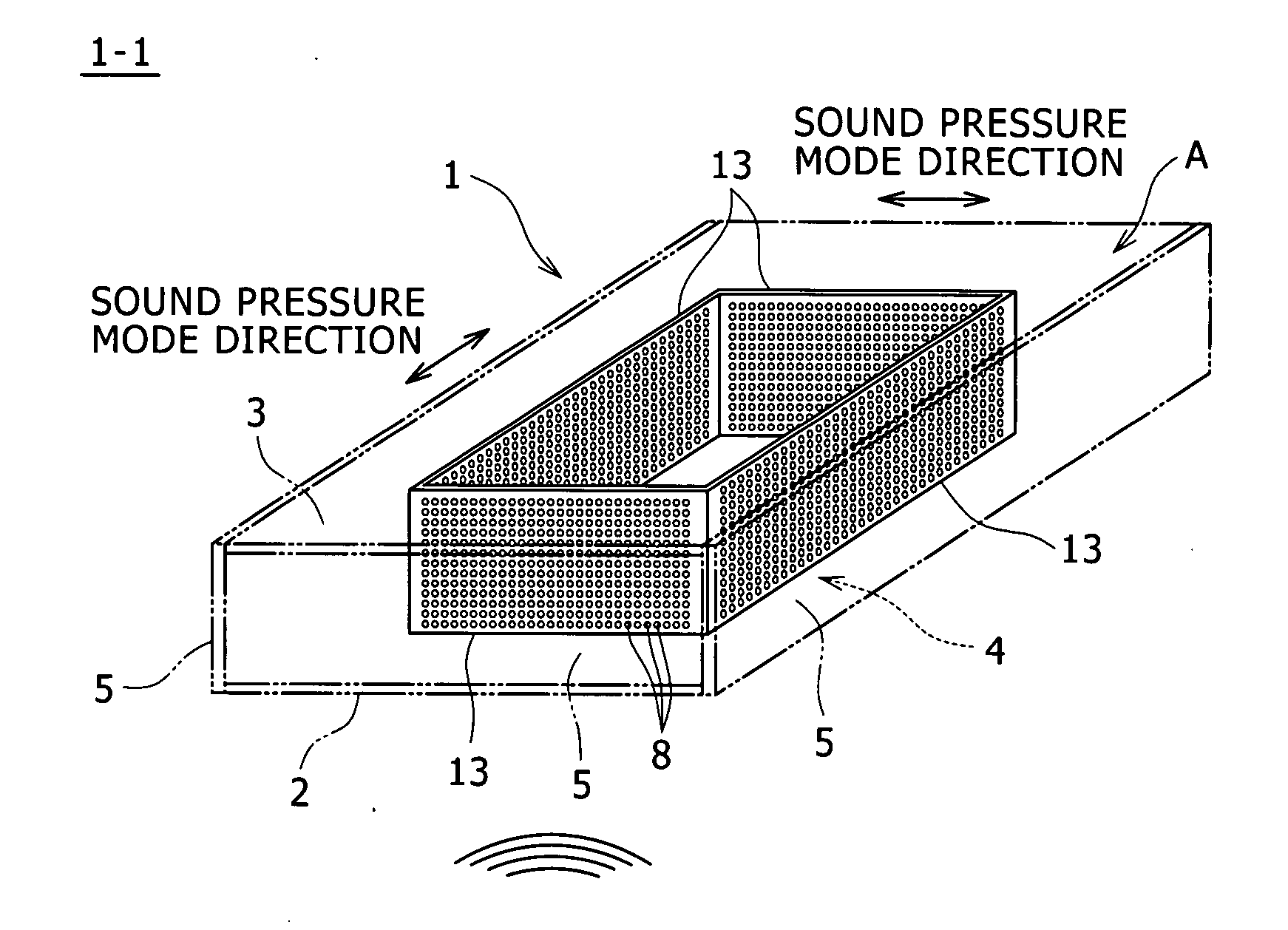
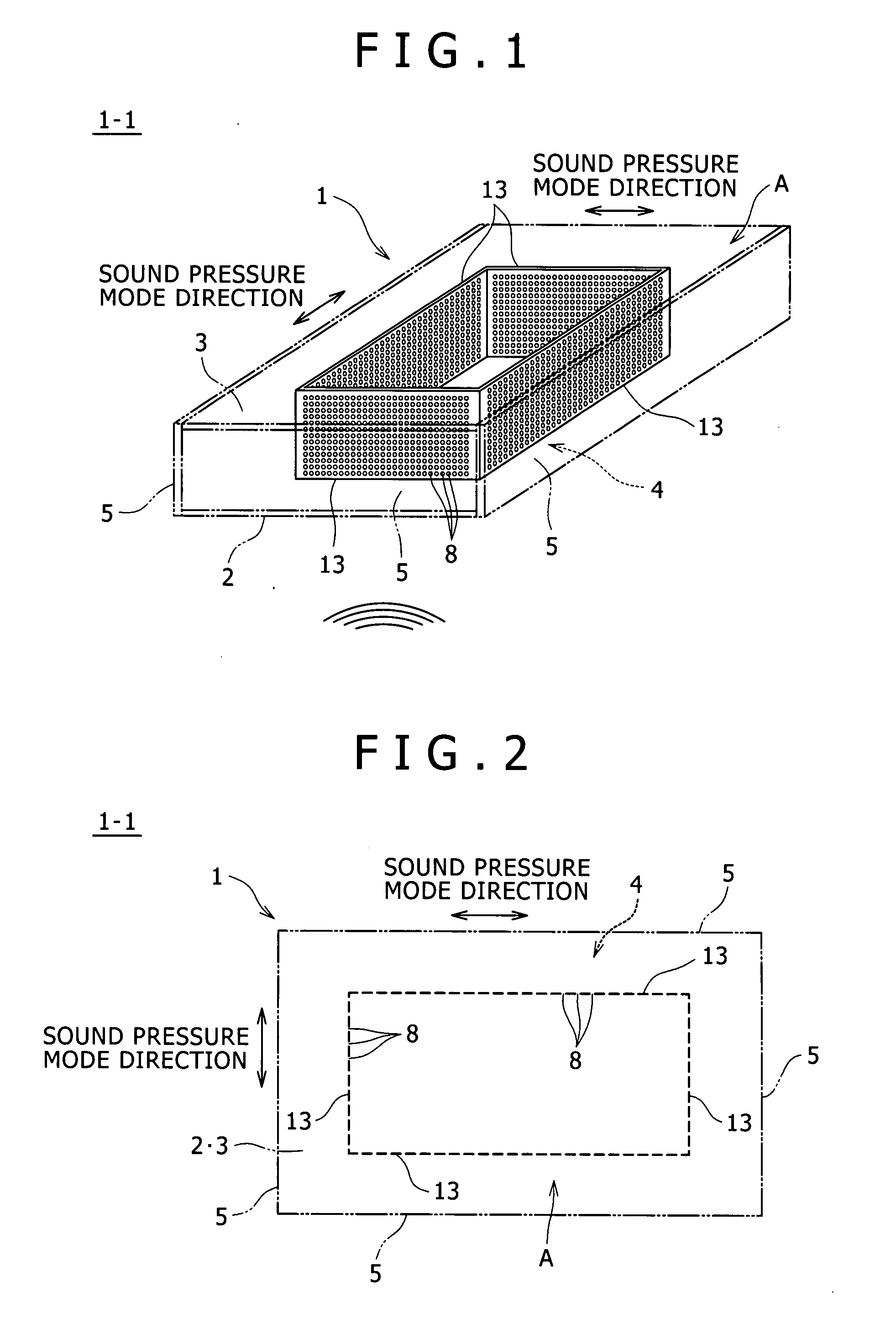
[0047]A double-wall structure of embodiment 1-1 shown schematically in FIGS. 1 and 2 assumes a door as a part of a passenger car. This double-wall structure, indicated at 1, has plate-like members 2 and 3 disposed in parallel with each other and opposed to each other at a predetermined distance. The plate-like members 2 and 3 are each formed in a rectangular shape which is a little longer in one direction and an air space 4 is formed between the two opposed plate-like members 2 and 3. Four side plates (circumferential members) 5 are disposed so as to connect edges of the plate-like members 2 and 3 with one another, whereby the air space 4 is closed substantially. In other words, with the plate-like members 2, 3 as double walls and the side plates 5, the double-wall structure of this embodiment is constituted as a bag structure which encloses the air space 4.

[0048]In this embodiment, finely perforated rectangular plates 13 are disposed so as to partition the air space...

second embodiment

See FIGS. 7 to 12

[0053]According to the configuration of embodiment 2-1 (FIG. 7), which is a modification of embodiment 1-1 (FIGS. 1 and 2), plural plate-like partition members 9 are provided so as to provide connections between side plates 5 and finely perforated plates 13. With the partition members 9, the layer of air A interposed between the side plates 5 and the finely perforated plates 13 is partitioned in both longitudinal and transverse directions of the double-wall structure 1. It is preferable that the partition members 9 be disposed at positions where a resonance phenomenon occurring in the extending direction of the layer of air between the finely perforated plates 13 and the side plates 5 is difficult to occur at a desired frequency. More specifically, the partition members 9 are disposed at a spacing not coinciding with an integer multiple of a half of the wavelength for the frequency intended to improve the sound insulating performance. As a result, it is possible to ...

third embodiment

See FIGS. 13 and 14

[0058]FIG. 13 is a sectional view of a double-wall structure 1 according to embodiment 3-1-1. As shown in FIG. 13, there is a case where a finely perforated plate 13 cannot contact the plate-like member 2 on the vibration generating side and the plate-like member 3 on the opposite side in a completely airtight manner and certain slits are formed. The absence of such slits is preferred, so in this embodiment a vibration damping / isolating member 16 formed of, for example, rubber or urethane is installed in each of the portions corresponding to the slits. As a result, it is possible to enhance the sound absorbing performance of sound absorbing mechanism. As shown in embodiment 3-1-2 (FIG. 14), the vibration damping / isolating member 16 may be disposed between the finely perforated plate 13 and only one of the two plate-like members 2 and 3. If the above slits are fine slits, the vibration damping / isolating member 16 may be omitted and it is possible to let the slits t...


PUM


Abstract

A double-wall structure (1), comprising plate-like bodies (2) and (3) disposed oppositely to each other to form an inner room (4) therebetween, peripheral members (5) disposed so that the inner room (4) can be completely or approximately closed, and perforated plates (13) with a large number of holes (8) disposed between the plate-like bodies facing each other. The double-wall structure is characterized in that an air layer (A) is interposed between the perforated plates and the peripheral members. Thus, since the double-wall structure can suppress the deterioration of a sound reduction index for sound with specific frequencies, it can stably develop sound insulation performance for sound with the various frequencies.

Description

FIELD OF ART[0001]The present invention relates to a double-wall structure.BACKGROUND ART[0002]It has heretofore been proposed to use a double-wall structure as automobile parts such as doors, hood and a trunk lid. For example, a conventional double-wall structure is a hollow box-like structure (bag structure) wherein an air space is formed between plate-like members opposed to each other at a predetermined distance, the air space being closed with side plates. In this conventional double-wall structure, however, when a sound wave of noise containing a sound component of a specific frequency is incident from below on the double-wall structure, there occurs resonance (mainly resonance in a direction parallel to the plate members) in the air space against the sound component. This causes an increase in amplitude of the upper plate-like member as a radiation plane and the resulting increase of a radiation sound deteriorates the sound insulating performance. Further, the conventional do...

Claims


Application Information

Patent Timeline
IPC IPC(8): E04B1/82
CPCB60J5/0418G10K11/172B60R13/0815B60R13/08
Inventor TSUGIHASHI, KAZUKITANAKA, TOSHIMITSUUEDA, HIROKI
Owner KOBE STEEL LTD
Why Eureka
Try Eureka