Sound Absorbing Structure

a sound absorbing structure and sound technology, applied in the field of sound absorbing structures, can solve the problems of inability to achieve a sound absorbing coefficient of 0.4 or higher, and the sound absorbing performance cannot be fully exercised to noise, and achieve the effect of facilitating processing and excellent sound absorbing performan

Inactive Publication Date: 2008-06-05
KOBE STEEL LTD
View PDF4 Cites 35 Cited by
  • Summary
  • Abstract
  • Description
  • Claims
  • Application Information

AI Technical Summary

Benefits of technology

[0023]As described, by allowing the fiber material and the perforated panel to have the relative relationship, in other words, by allowing the fiber material and the perforated panel to satisfy Equation (1) above and Equation (2) above respectively, even in the case there the perforated panel is a thin plate such as the alum

Problems solved by technology

Therefore, there are cases where sound absorbing performance cannot be fully exercised to noise including a plurality of frequencies as a peak component on sound absorbing performance, and sound absorbing coefficient becomes less than 0.4.
Therefore, to

Method used


Image

  • Sound Absorbing Structure
  • Sound Absorbing Structure
  • Sound Absorbing Structure

Examples


examples

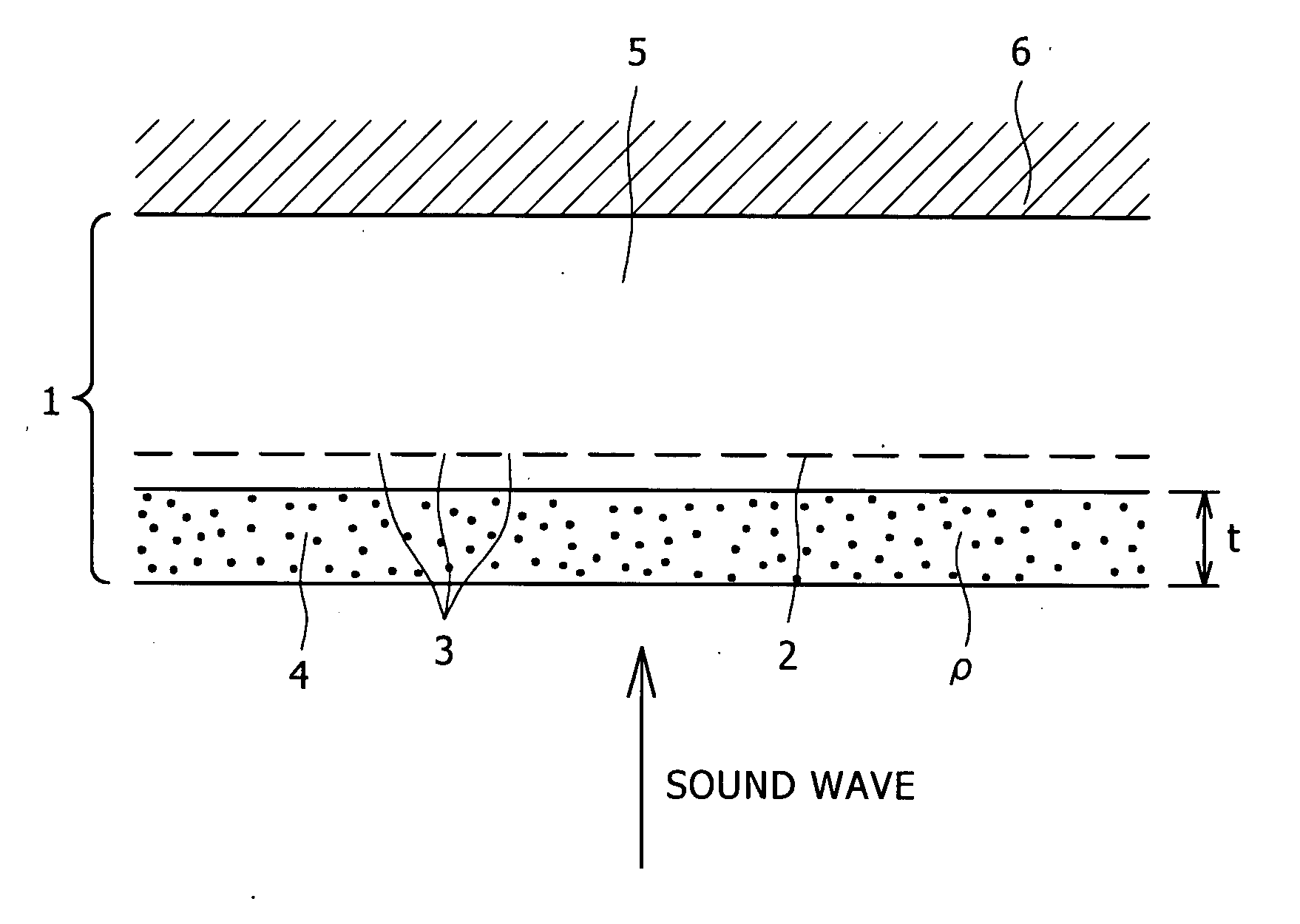
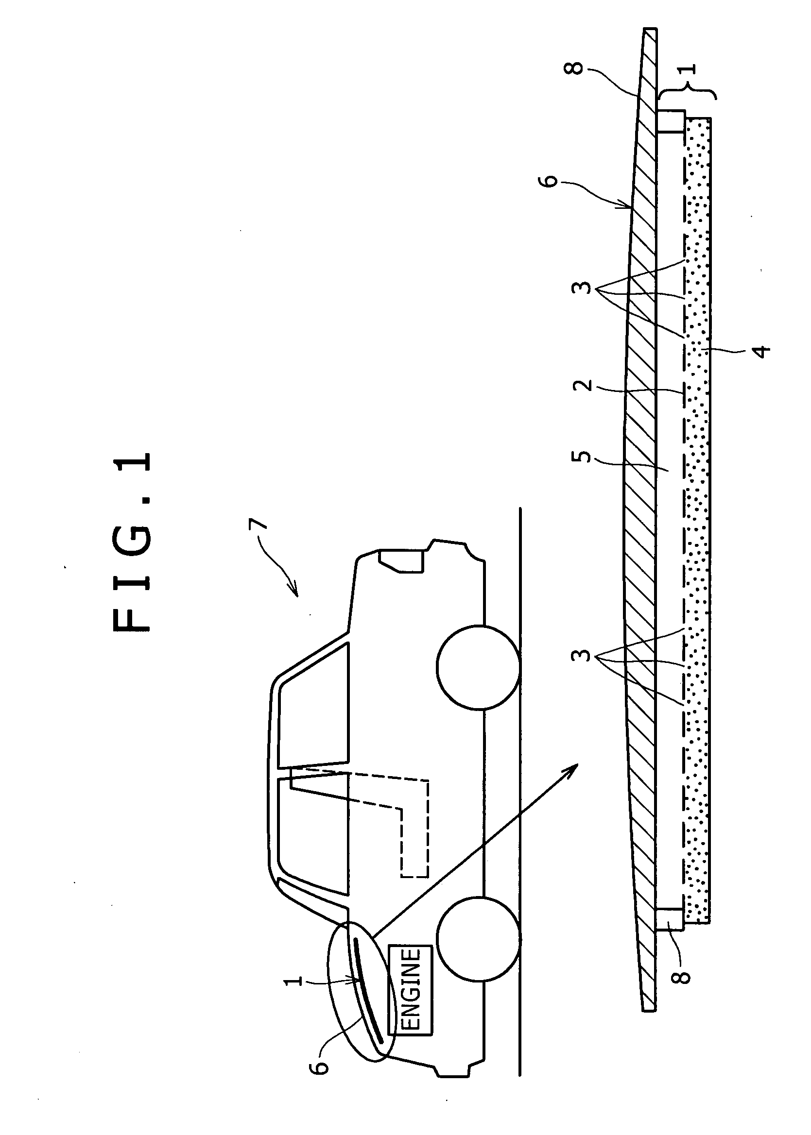
[0093]Next, examples of the present invention will be described. The sound absorbing structure 1 having the shape structure shown in FIG. 1 was prepared, ρ and t of the fiber material in Equation (1) were changed, a relationship between the hole diameter and the aperture ratio of the perforated panel, at which the sound absorbing coefficient of 0.4 or higher can be achieved was found from Equation (2).

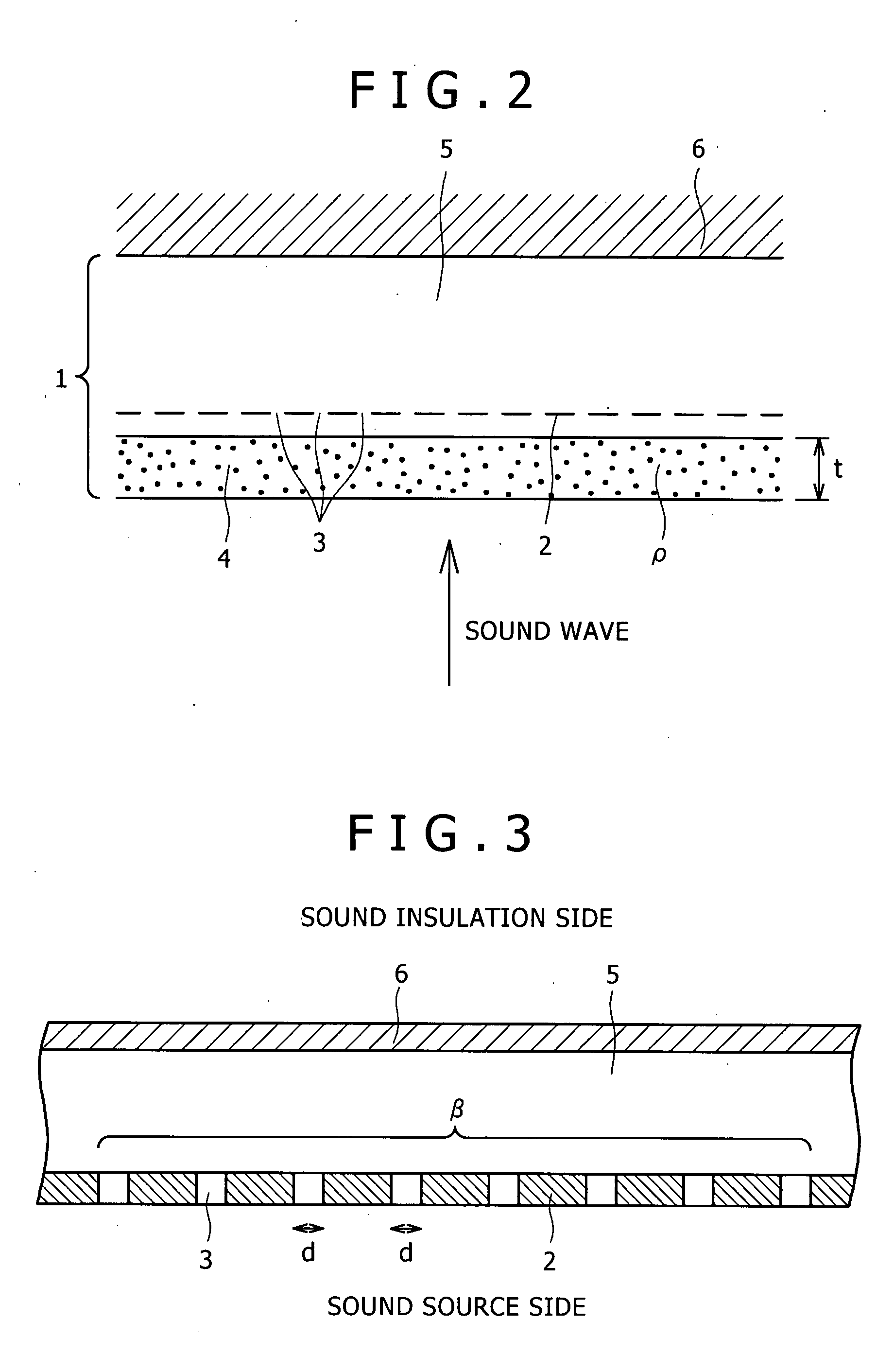
[0094]Regarding the sound absorption measurement, the sound absorbing coefficient was measured using a sounding tube. First, one end of the sounding tube was used as rigid wall plate (simulated hood panel), and a speaker being a sound source was arranged on the other end. The fiber material 4 was placed upright in front of the speaker with a fixed gap provided, an aluminum foil in which multiple holes were formed, which is the perforated panel 2, was placed upright so as to overlap behind the fiber material 4, and air layer 5 was allowed to exist in the rigid wall surface behind the pe...

invention example

FIG. 15

[0099]Rock wool was used as the fiber material, density ρ: 138 kg / m3 and thickness t: 1.2 mm were set, and ρ×t=0.16 kg / m2 was set so as to satisfy ρ×t≧0.01 kg / m2 of Equation (1). FIG. 15 shows that an area(range) reaching the sound absorbing coefficient of 0.6 or higher has spread even if the hole diameter of the perforated panel is φ0.5 m or larger.


PUM


Abstract

A sound absorbing structure having excellent in sound absorbing performance, which is capable of achieving 0.4 or higher in the sound absorbing coefficient even in the case where a perforated panel is a thin plate such as aluminum foil within a range where a reduction in the weight of a vehicle body is not impaired and through holes have a large hole diameter in order to make the processing of providing a large number of through holes in the perforated panel. The sound absorbing structure 1 is the sound absorbing structure 1 for suppressing noise generated on a sound source side, which is equipped with: a perforated panel 2 having a large number of through holes 3 and a fiber material 4, which are provided so as to face the sound source side and provided so as to overlap with each other; and an air layer 5 provided behind the perforated panel 2, in which the density and the thickness of the fiber material 4 and the hole diameter and the aperture rate of the through holes 3 of the perforated panel 2 severally have a specific relationship.

Description

FIELD OF THE INVENTION[0001]The present invention relates to a sound absorbing structure having excellent in sound absorbing performance, which is capable of achieving 0.4 or higher in sound absorbing coefficient, and to a sound absorbing structure applicable for vehicle application such as an automotive vehicle, structure application such as a sound barrier and a tunnel inner wall, or the application of various fields in which another sound absorption is necessary.TECHNICAL FIELD[0002]The explanation below will be made by taking the vehicle application being a main application as an example out of various fields in which sound absorption by a sound absorbing structure according to the present invention is necessary.[0003]In recent years, automotive vehicles are required to suppress noise generated on a sound source side of vehicle for more comfortable vehicle drive. For example, in an engine hood of an automotive vehicle, sound absorbing effect to absorb and reduce engine sound ins...

Claims


Application Information

Patent Timeline
IPC IPC(8): E04B1/82
CPCB32B3/266B60R13/0838G10K11/16B60R13/0876B60R13/0884B60R13/0861
Inventor YAMAGUCHI, ZENZOYAMAGIWA, ICHIROTANAKA, TOSHIMITSUUEDA, HIROKITSUBOTA, KENSUKE
Owner KOBE STEEL LTD
Why Eureka
Try Eureka