Energy Recovering Method and System in Hydraulic Lift Device of Battery Operated Industrial Trucks

a technology of energy recovery and hydraulic lift, which is applied in the direction of elevators, instruments, fluid couplings, etc., to achieve the effects of reducing the responsivity of speed change, reducing the total weight of the system, and saving installation spa

Active Publication Date: 2008-06-05
NIPPON YUSOKI
View PDF12 Cites 26 Cited by
  • Summary
  • Abstract
  • Description
  • Claims
  • Application Information

AI Technical Summary

Benefits of technology

[0010]The present invention was made in light of the problems of the prior art, and the object of the invention is to provide a method and a compact system for recovering the potential energy generated by a hydraulic lift device in a battery operated industrial tracks such as a forklift truck or the like, in which working fluid can be supplied to other actuators while performing the energy recovering operation, occurrence of oil pressure pulsation in the energy recovering operation is prevented, operability is increased, and energy recovering efficiency is improved.

Problems solved by technology

Further, when torque is deficient to rotate the hydraulic pump to allow it to work as a hydraulic motor because of light weigh of the load on the lift means, the electric motor is rotated before the control valve is opened in the initial stage of the lowering operation.

Method used


Image

  • Energy Recovering Method and System in Hydraulic Lift Device of Battery Operated Industrial Trucks
  • Energy Recovering Method and System in Hydraulic Lift Device of Battery Operated Industrial Trucks
  • Energy Recovering Method and System in Hydraulic Lift Device of Battery Operated Industrial Trucks

Examples


first embodiment

The First Embodiment

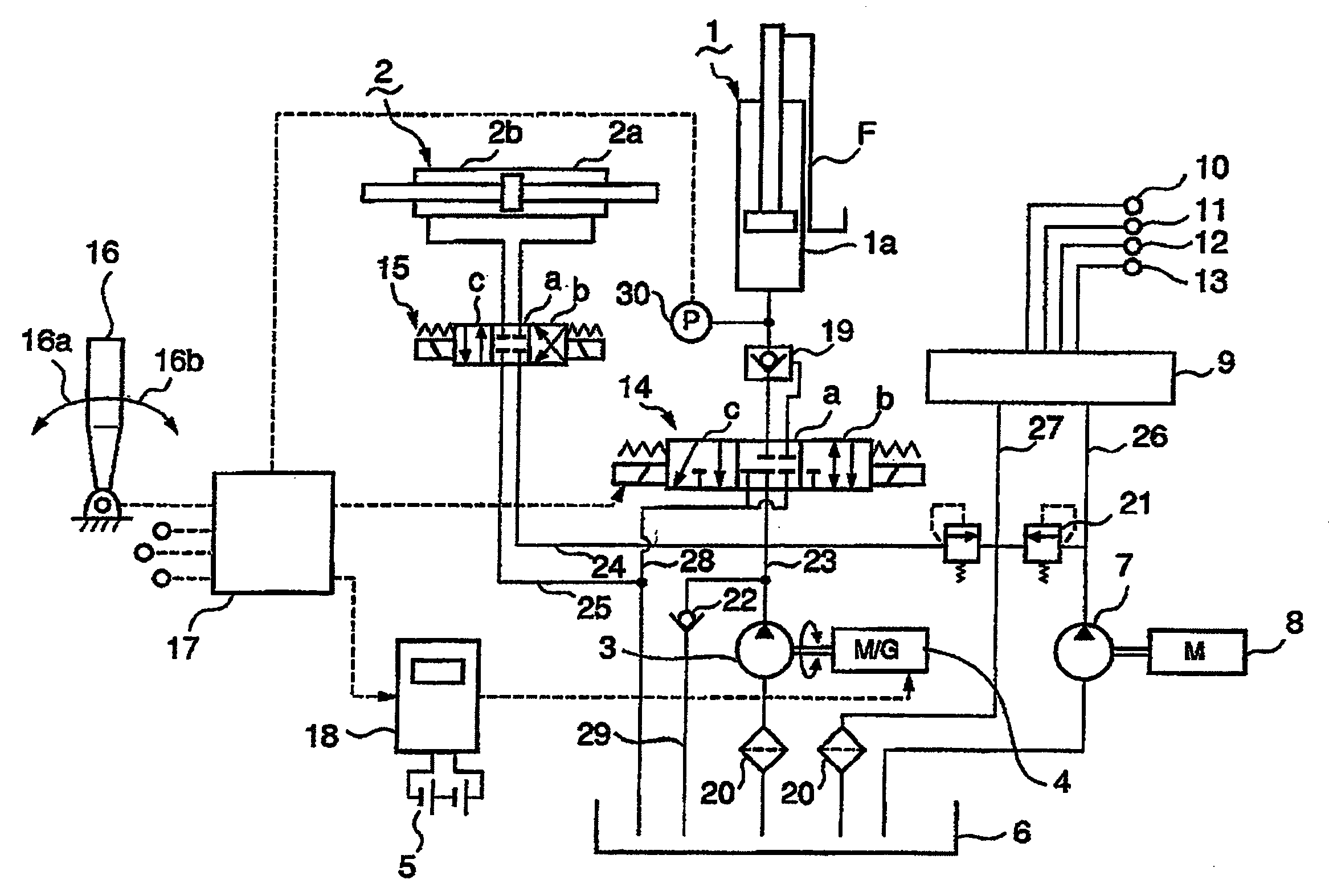
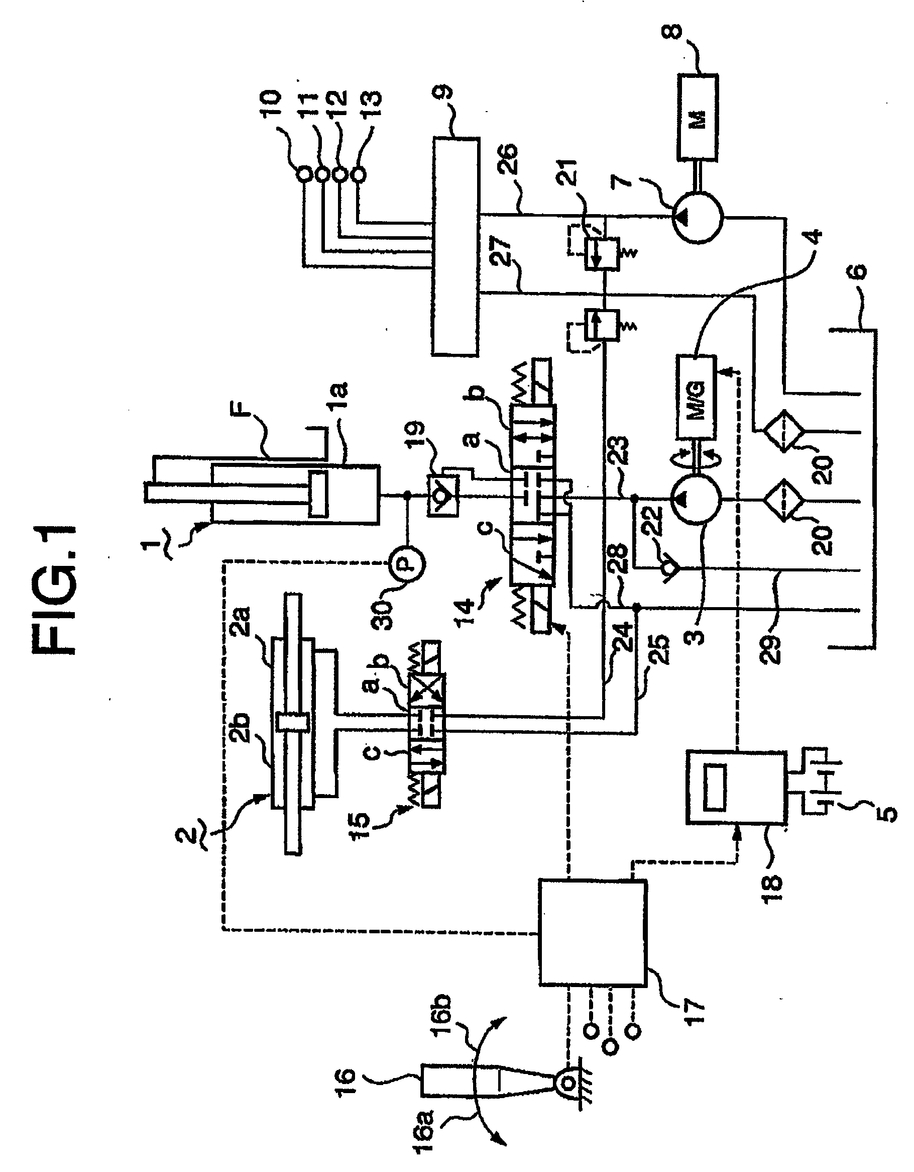
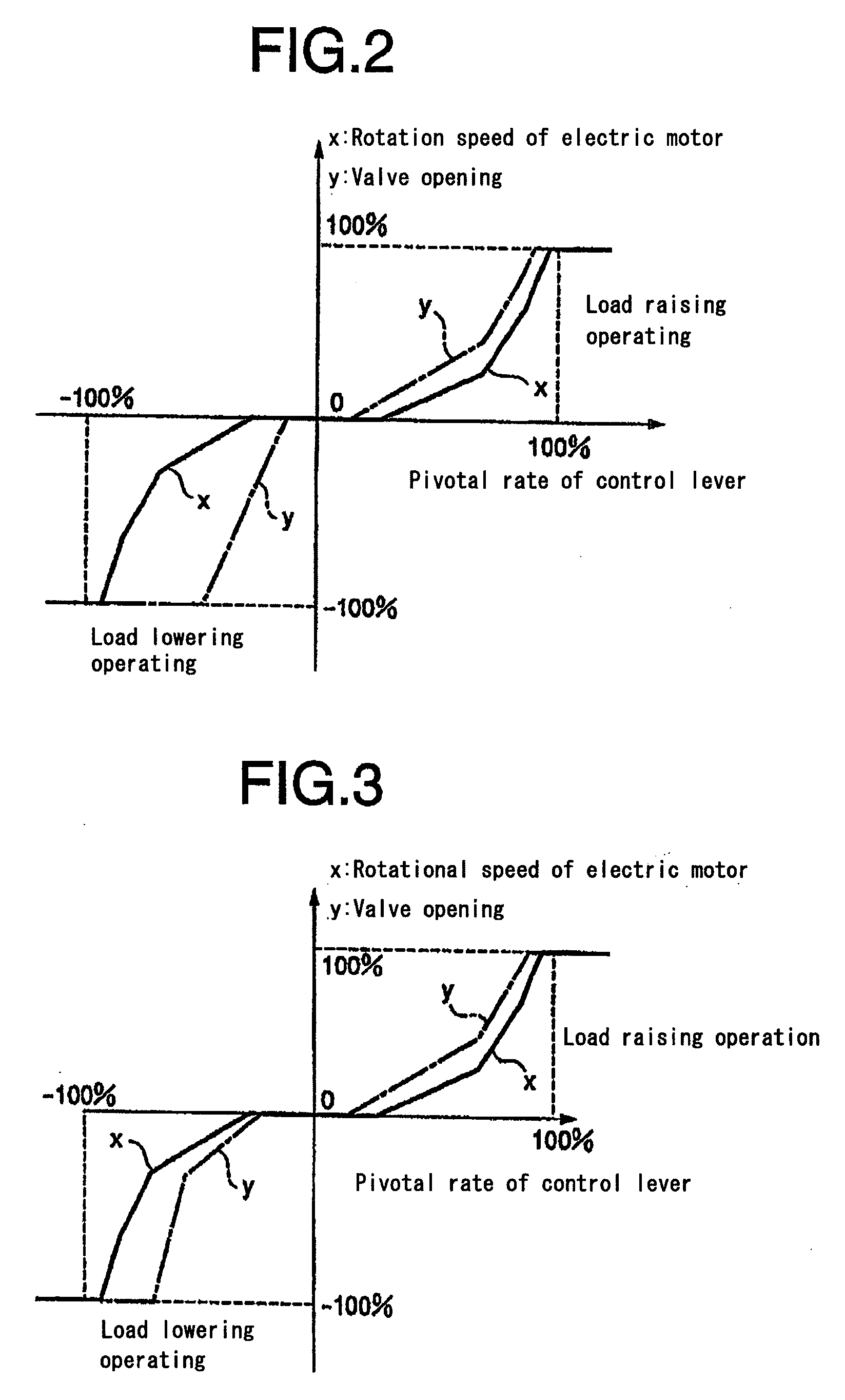
[0053]FIG. 1 is a schematic hydraulic lift circuit of the first embodiment according to the invention, and FIG. 2 is a diagram showing rotation speed x of the electric motor and the amount of opening of the control valve 14 vs. the pivotal rate y of the control lever in the first embodiment.

[0054]In FIG. 1, reference numeral 1 is a lift cylinder for lifting a fork F (lift means) of a forklift truck, 1a is a bottom oil chamber of the lift cylinder 1, 2 is a hydraulic cylinder composing a second actuator for driving another attachment of the forklift truck, for example, a driving device for driving claws not shown of the fork F. Reference numeral 3 is a hydraulic pump for supplying working oil from an oil tank 6 to oil chambers of the lift cylinder 1 and hydraulic cylinder 2, 5 is a set of batteries for supplying electricity to the electric motor 4.

[0055]Reference numeral 7 is a second hydraulic pump, which is driven by an electric motor 8, sucks the working oil in...

second embodiment

The Second Embodiment

[0063]FIG. 3 shows another example (the second embodiment) of controlling the lowering speed through the control of rotation speed of the electric motor 4 and the opening of the control valve 14 in the lowering operation. In the embodiment, as shown in FIG. 3, the lowering speed is controlled by controlling the opening of the control valve 14 in the initial range where the lowering speed is small and gentle control of the lowering speed is needed, and the lowering speed is controlled through the control of rotation speed of the electric motor 4 with the opening of the control valve 14 being steeply increased in the range where the lowering speed is large as is at the rated speed lowering. In this way, energy recovery efficiency can be increased by performing delicate control of the lowering speed.

third embodiment

The Third Embodiment

[0064]FIG. 4 shows a further example (the third embodiment) of controlling the raising and lowering speed of the fork F. In the system of the first embodiment shown in FIG. 1, oil pressure P in the bottom oil chamber 1a of the lift cylinder 1, which pressure being dependent on the weight of the load, is detected by the pressure sensor 30, and the opening of the control valve 14 and the rotation speed of the electric motor 4 with respect to the pivotal rate of the control lever 16 are controlled according to the detected pressure P.

[0065]By controlling with the weight of the load on the fork F taken into consideration like this, the lowering of the fork F when the load on the fork F is heavy is performed smoothly, and energy recovery efficiency can be increased.


PUM


Abstract

An energy recovering system in a hydraulic lift device of a battery operated industrial truck. With the system, working oil can be supplied to other hydraulic actuators while energy recovering operation is performed by the hydraulic lift device, occurrence of pressure pulsation in the working oil can be prevented, and energy recovering efficiency is increased. The hydraulic lift device comprises a lift cylinder (1) for lifting a fork F, an electric motor (4) rotated by power supply from a battery (5), a hydraulic pump (3) for supplying pressurized oil to the lift cylinder (1), a control valve (14) disposed in a pressurized oil supply path (23), and a controller (17). The controller (17) controls the opening of the control valve (14) and rotation speed of the electric motor (4) which functions as an electric generator driven by the hydraulic pump (3) rotated by the action of the pressurized oil returning from the lift cylinder (1) when a load is lowered so that the generated electricity charges the battery (5) to recover the potential energy of the load.

Description

TECHNICAL FIELD[0001]The present invention relates to a method and system for recovering the potential energy generated by a hydraulic lift device of a battery operated industrial tracks such as a forklift truck or the like, in which a hydraulic pump for supplying pressurized working fluid to a lift cylinder to raise a load is allowed to work as a hydraulic motor by allowing the pressurized working fluid to return from the lift cylinder to the hydraulic pump when the load is lowered, and an electric motor for driving the hydraulic pump is allowed to work as an electric generator to charge the battery to recover the potential energy of the load. The system can be composed to be compact and capable of supplying working fluid to other hydraulic actuators while the load lowering operation is carried out. Further, occurrence of pressure pulsation in the working oil can be prevented, operability is improved, and energy recovering efficiency is increased.BACKGROUND ART[0002]As a battery op...

Claims


Application Information

Patent Timeline
Patent Type & Authority Applications(United States)
IPC IPC(8): B66F9/20B66F9/22B66F9/24
CPCB66F9/22B66F9/24F15B21/14F15B2211/88F15B2211/20561F15B2211/6313F15B2211/20515Y02P80/10
Inventor TAHASHI, KENSUKESATOU, HIROSHIKAWAGUCHI, MASATAKAAKAGI, TOMOHIROEGUCHI, FUJIOOGINO, KEIZOYUGUCHI, SHINGOKAWASHIMA, KAZUSHIAKAO, MICHIO
Owner NIPPON YUSOKI
Why Eureka
Try Eureka