Imaging device camera system and driving method of the same

Inactive Publication Date: 2008-06-05
SONY SEMICON SOLUTIONS CORP
View PDF8 Cites 69 Cited by
  • Summary
  • Abstract
  • Description
  • Claims
  • Application Information

AI Technical Summary

Benefits of technology

[0010]Thus, it is desirable to provide an imaging device and a camera system with excellent color reproducibility which can improve resoluti

Problems solved by technology

However, in the imaging device described above, the apparatus has limitations on the improvement of resolution and color reproducibility.
In addition, it is difficult to control color

Method used


Image

  • Imaging device camera system and driving method of the same
  • Imaging device camera system and driving method of the same
  • Imaging device camera system and driving method of the same

Examples


Embodiment Construction

[0065]Hereinafter, an embodiment of the invention will be described with reference to the drawings.

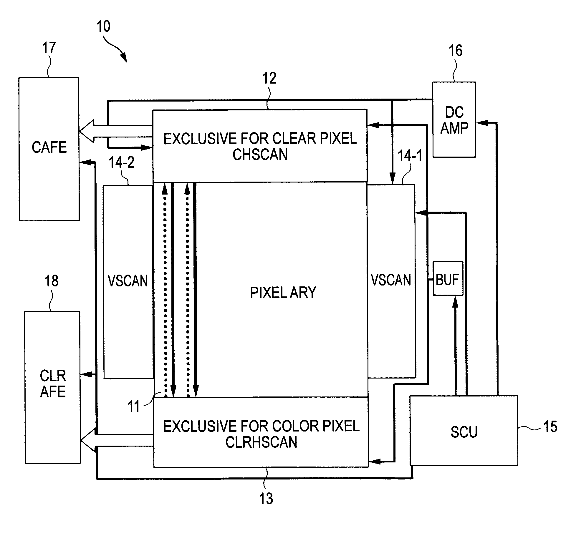
[0066]FIG. 1 shows a block diagram depicting an exemplary configuration of the essential part of an imaging device according to an embodiment of the invention.

[0067]As shown in FIG. 1, an imaging device 10 has a pixel array part (ARY) 11, a clear pixel horizontal scanning circuit (CHSCAN) 12, a color pixel horizontal scanning circuit (CLRHSCAN) 13, a vertical scanning circuits (VSCAN) 14-1 and 14-2, a timing control part 15, a power source part 16, a clear pixel analog front end part (CAFE) 17, and a color pixel analog front end part (CLRAFE) 18.

[0068]For example, in the pixel array part 11, sensor unit pixels are arranged in an array in a predetermined arrangement form.

[0069]In addition, the pixel array part 11 is wired with a transfer selection line, a reset line, and a select line in each row in the pixel arrangement, and a signal line in each column in the pixel arrangement.
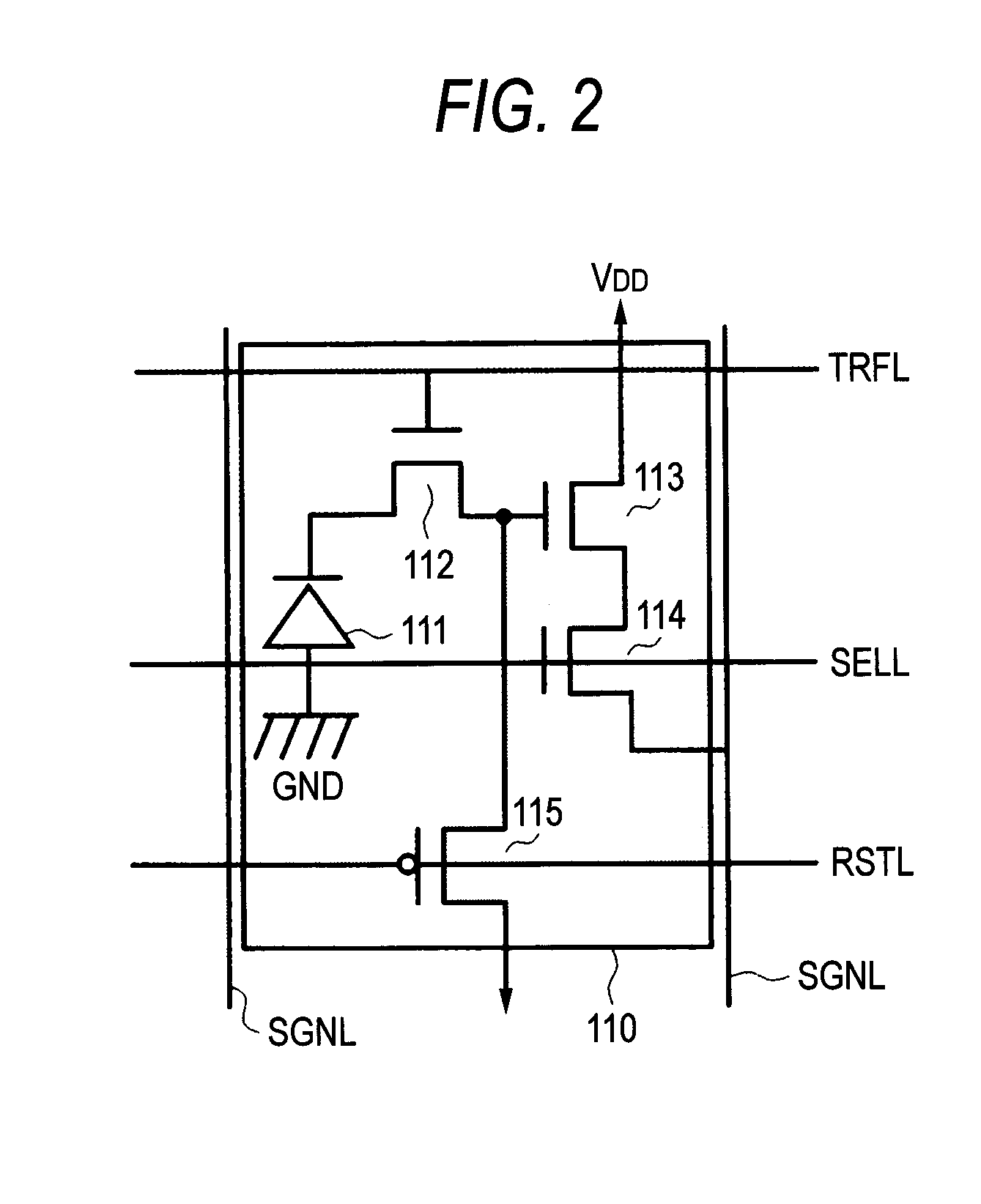
[0070]F...


PUM


Abstract

An imaging device includes: a pixel array part in which a plurality of pixels with different characteristics of spectral sensitivity are arranged in an array and which converts light transmitted through the pixel into an electric signal, wherein in the pixel array part, among a first color filter pixel, a second color filter pixel, and a third color filter pixel, each including a color filter, at least a plurality of the first color filter pixels and the second color filter pixels is arranged in an oblique pixel array system, and a clear pixel having a high transmittance is arranged in an oblique pixel array system at a given position of a given row and a given column in the oblique pixel array with respect to the first color filter pixel, the second color filter pixel, and the third color filter pixel.

Description

CROSS REFERENCES TO RELATED APPLICATIONS[0001]The present invention contains subject matter related to Japanese Patent Application JP 2006-100931 filed in the Japanese Patent Office on Mar. 31, 2006, the entire contents of which being incorporated herein by reference.BACKGROUND OF THE INVENTION[0002]1. Field of the Invention[0003]The present invention relates to an imaging device, a camera system and a driving method of the same, provided with a solid state imaging device such as a CCD (Charge Coupled Device), and a CMOS (Complementary Metal Oxide Semiconductor) sensor, particularly to an imaging device and a camera system in which in a two dimensional pixel array using a plurality of color filters, the pixel arrangement and the pixel array are sequentially scanned for exposure and read operation.[0004]2. Description of the Related Art[0005]For a color filter arrangement of an imaging device, the Bayer array is known which uses two green (G) filters, a single red (R) filter, and a s...

Claims


Application Information

Patent Timeline
IPC IPC(8): G01J3/02H01L27/14H01L27/146H04N9/07
CPCH01L27/14603H01L27/14621H04N5/3458H04N2209/045H04N5/3535H04N5/35554H04N9/045H04N5/3532H01L27/14605H01L27/1461H01L27/14627H01L27/14645H01L27/14689H01L27/14647H04N25/531H04N25/533H04N25/583H04N25/447H04N25/135H04N23/843H04N23/10H04N23/12H04N25/534H01L21/266
Inventor KANAI, JUNICHINAKAMURA, NOBUO
Owner SONY SEMICON SOLUTIONS CORP
Why Eureka
Try Eureka