Tire manufacturing method

Inactive Publication Date: 2008-06-05
SUMITOMO RUBBER IND LTD
View PDF2 Cites 22 Cited by
  • Summary
  • Abstract
  • Description
  • Claims
  • Application Information

AI Technical Summary

Benefits of technology

[0016]A shape of the bead influences various performances of the tire. The shape of the bead is important. In the present invention, the bead is vulcanized and formed with an interposition between the mold and the insert core. Therefore, the shape of the bead is coincident with a designed shape. In the present invention, the portion of the inner peripheral surface of the green tire which does not abut on the insert core is pressurized by the bladder. An applied pressure is high. The insert core to be used in the p

Problems solved by technology

Since the bladder is formed of a rubber, precision in a shape in the expansion is not sufficient.
A shape of the inner surface of the tire cannot be controlled easily.
In some cases, the rubber composition of the green tire causes an unintended flow by the abutment.
When the shape of the bladder is nonuniform, furthermore, a uniformity of the tire is impeded.
The insert core is generally expensive.
A high cost is required

Method used


Image

  • Tire manufacturing method
  • Tire manufacturing method
  • Tire manufacturing method

Examples


example 1

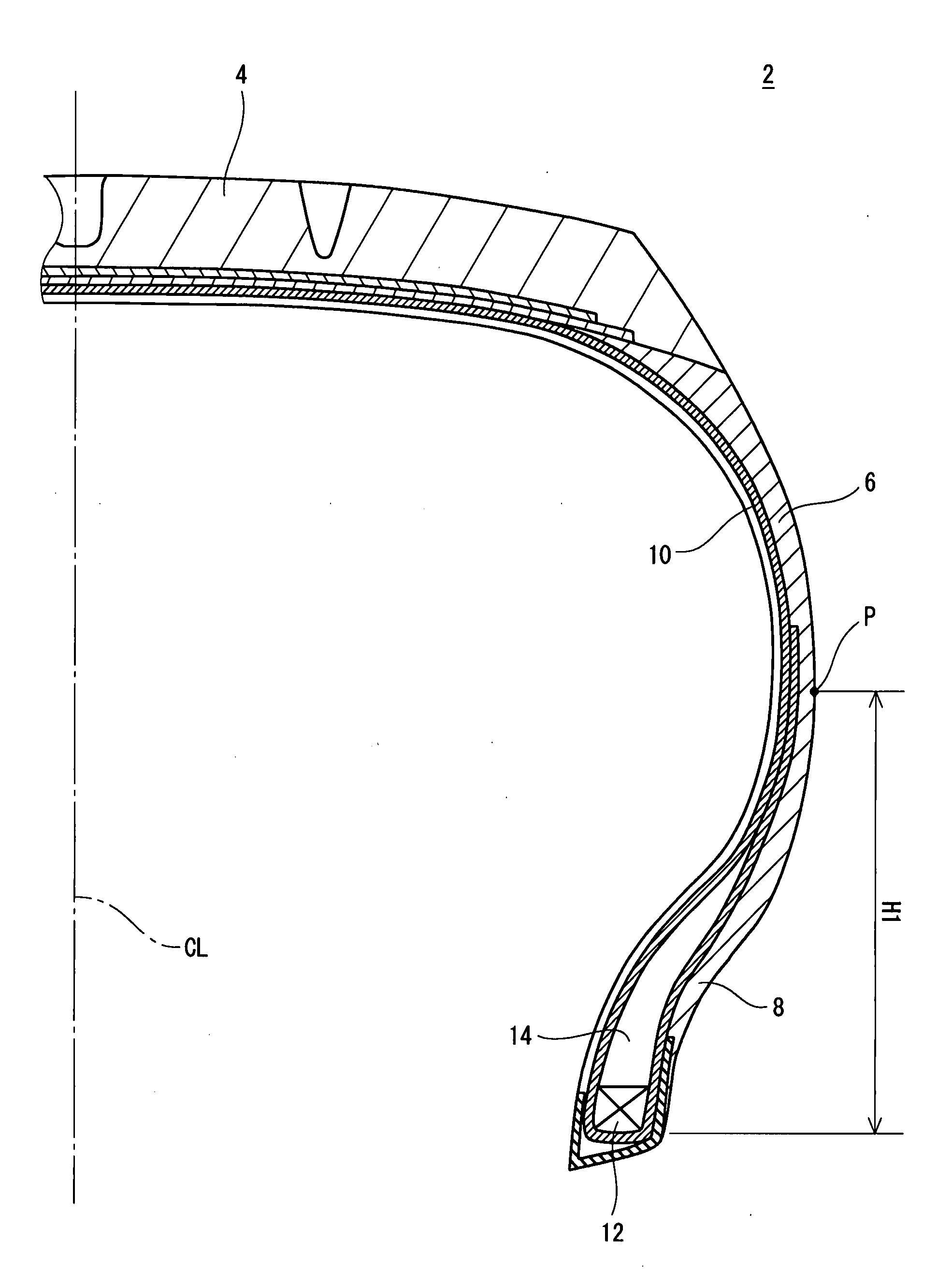
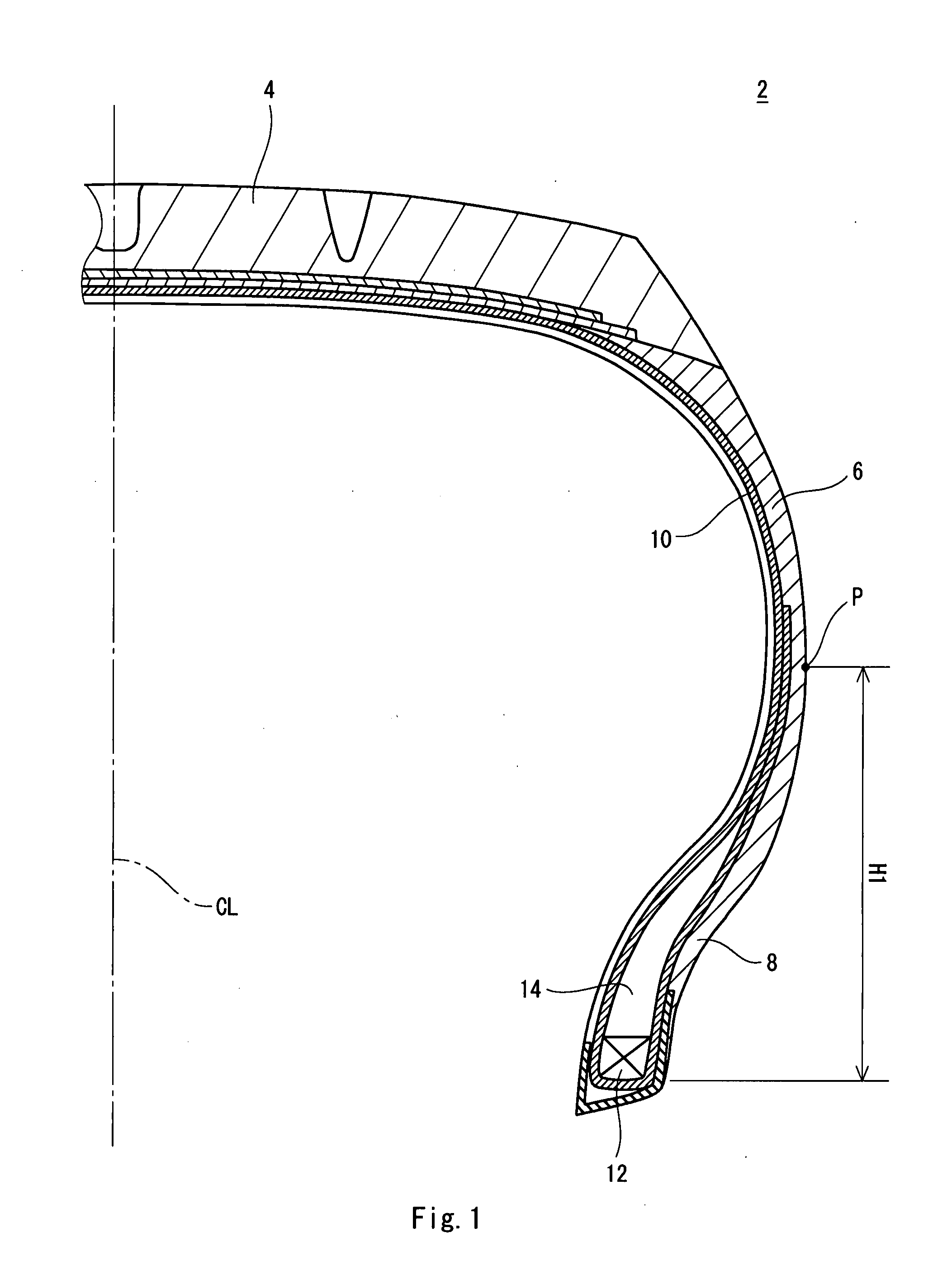
[0040]A tire was manufactured by using the mold, the insert core and the bladder shown in FIGS. 2 to 4. The distance L of the insert core is 26 mm. The distance L is equal to the height H3 of the upper end of the apex. The tire has a size of “215 / 45ZR17”. The tire comprises a carcass ply. The carcass ply is turned up around a core. A height He of an end of a turned-up portion from the bead baseline BL is 20 mm. A height (H3−H2) of the apex in the tire is 20 mm.

examples 2 to 4 and 6

[0041]A tire was manufactured in the same manner as in the example 1 except that the insert core was changed. The distance L of the insert core is shown in the following Table 1. In an example 2, the distance L is smaller than the height H2. In an example 3, the distance L is equal to the height H2. In an example 4, the distance L is greater than the height H2 and is smaller than the height H3. In an example 6, the distance L is equal to the height H1.

example 5

[0042]A tire was manufactured in the same manner as in the example 1 except that the height He of the end of the carcass ply was set as shown in the following Table 1.

[Evaluation of Uniformity]

[0043]RFV was measured in accordance with a condition of a uniformity test defined in “JASO C607:2000”. A mean value of results obtained by measuring 20 tires is shown in the following Table 1.

[Sensuous Evaluation]

[0044]A tire was incorporated into a rim, and the tire and the rim were attached to a passenger car. The car is of a front engine rear wheel drive type. The car has an engine displacement of 3000 cc. The car was caused to carry out high speed running in a racing circuit and a response characteristic was rated by a driver. The result is shown in the following Table 1. A greater numeric value represents a higher evaluation.

TABLE 1Result of evaluationComparativeexample 1Example 2Example 3Example 4Example 5Example 1Example 6Distance of insert core L—3618262647(mm)(L (L = H2)(H2 (L = H3)(...


PUM

PropertyMeasurementUnit
Diameteraaaaaaaaaa
Widthaaaaaaaaaa
Internal pressureaaaaaaaaaa

Abstract

A green tire (20) is put into a mold (16) in which an insert core (18) and a bladder (22) are accommodated. In the putting operation, a diameter of the insert core (18) is reduced and the bladder (22) is contracted. After the putting operation, the diameter of the insert core (18) is increased so that an inner surface of a bead (8) of the green time (20) abuts on an insert core plate (36). The bead is interposed between the insert core (18) and a cavity surface (34). By filling a gas, the bladder (22) is gradually expanded. The mold (16) is clamped so that an internal pressure of the bladder (22) is further raised. A portion of an inner peripheral surface of the green tire (20) which does not abut on the insert core (18) abuts on the bladder (22). The green tire (20) is heated by a thermal conduction from the mold (16) and the bladder (22).

Description

[0001]This application claims priority on Patent Application No. 2006-325423 filed in JAPAN on Dec. 1, 2006, the entire contents of which are hereby incorporated by reference.BACKGROUND OF THE INVENTION[0002]1. Field of the Invention[0003]The present invention relates to a method of manufacturing a tire. More particularly, the present invention relates to an improvement in a step of vulcanizing a tire.[0004]2. Description of the Related Art[0005]In a step of vulcanizing a pneumatic tire, a mold and a bladder are used. The mold is formed of a metal. The bladder is formed of a rubber. The bladder is accommodated in the mold. At the vulcanizing step, a green tire obtained in a preforming step is put into the opened mold. In the putting operation, the bladder is contracted. By the putting operation, the bladder is positioned on an inside of the green tire. The bladder is expanded by filling a gas. By the expansion, the green tire is deformed. The deformation is referred to as shaping. N...

Claims


Application Information

Patent Timeline
IPC IPC(8): B60C5/00B29C35/00
CPCB29D30/0601B29D2030/0621Y10T152/10495B29D2030/0625B29D2030/0622
Inventor SAKAMOTO, MASAYUKI
Owner SUMITOMO RUBBER IND LTD
Why Eureka
Try Eureka