Milling Machine with Cleaning Moldboard

a moldboard and milling machine technology, applied in cutting machines, roads, construction, etc., can solve the problems of poor bonding between the new asphalt and the milled surface, the persistence of prior existing conditions, and the accumulation of debris, so as to reduce friction, reduce the formation of dust particles, and effectively push

Inactive Publication Date: 2008-06-05
NOVATEK IP
View PDF9 Cites 18 Cited by
  • Summary
  • Abstract
  • Description
  • Claims
  • Application Information

AI Technical Summary

Benefits of technology

[0008]The plurality of nozzles may be utilized to provide fluid that effectively pushes aggregate towards the milling drum while at the same time substantially reducing any dust particles from forming. The fluid from the reservoir may also be utilized through the fluid pathway to reduce friction, absorb heat and remove any aggregate from the milling drum that may begin to build up when the milling drum is engaging the paved surface. As a result the milled surface may be substantially void of any residue material and promote better bonding for resurfacing.

Problems solved by technology

Resurfacing an existing road surface with such defects may result in a perpetuation of prior existing conditions, especially if the road surface is exposed to heavy and / or continuous traffic which often requires the road to be resurfaced again within a short period of time.
Typically the milling machines direct milled road fragments towards a conveyer which takes the fragments off the road, however, a significant amount of debris, aggregate, and fragments remain on the milled surface.
Failure to clear the milled surface of such material may result in poor bonding between the new asphalt and the milled surface.
Typically a sweeper will come along after the milling machine to remove of the debris, but often this is inefficient and uneconomical.

Method used


Image

  • Milling Machine with Cleaning Moldboard
  • Milling Machine with Cleaning Moldboard
  • Milling Machine with Cleaning Moldboard

Examples


Embodiment Construction

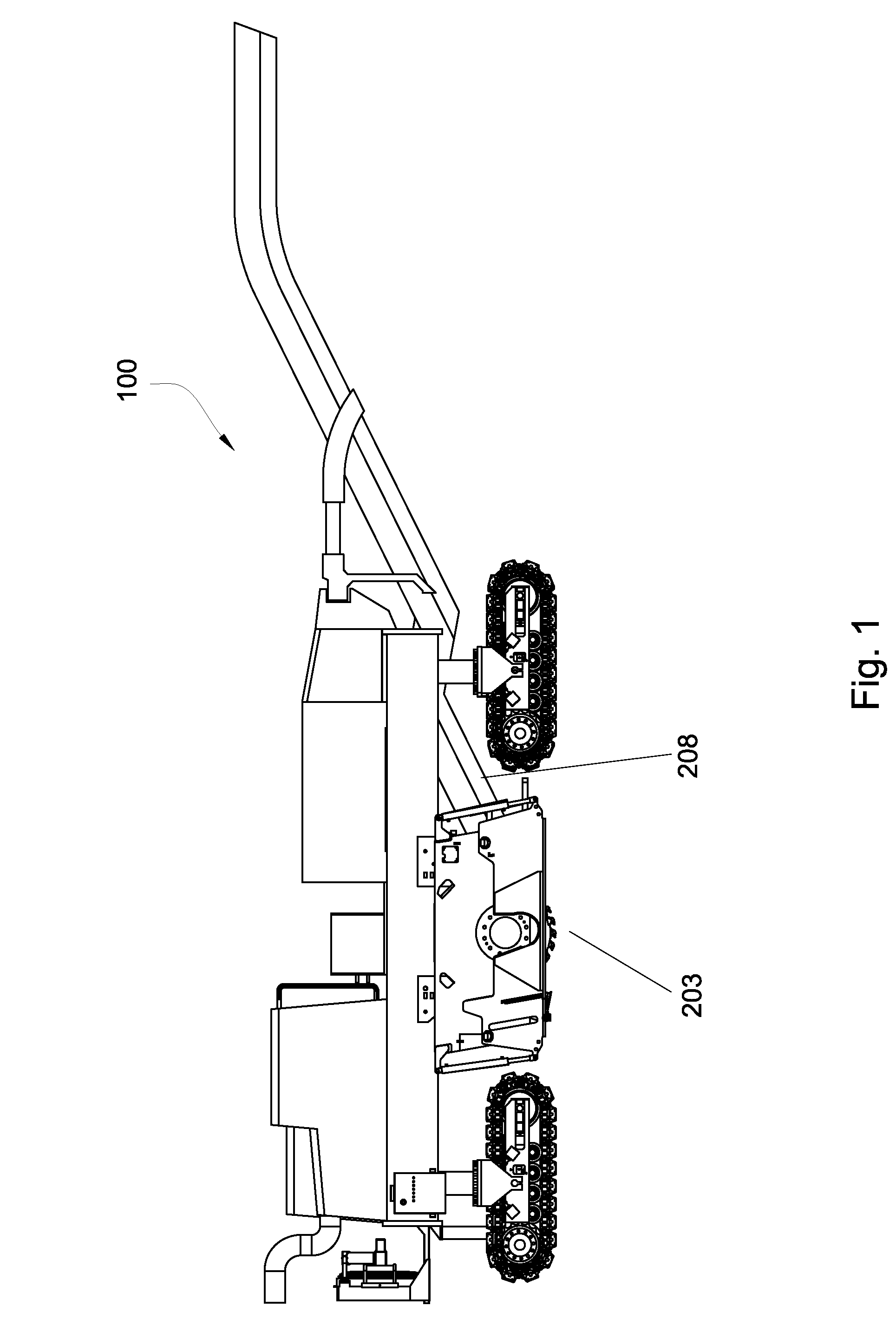
[0021]FIG. 1 depicts a milling machine 100 which may be used to remove asphalt from road surfaces. A milling drum 203 is attached to the underside of the frame of the milling machine 100. A conveyer 208 is adapted to take the millings off the road. Typically the millings are loaded into a bed of a truck (not shown) where the millings may be hauled away.

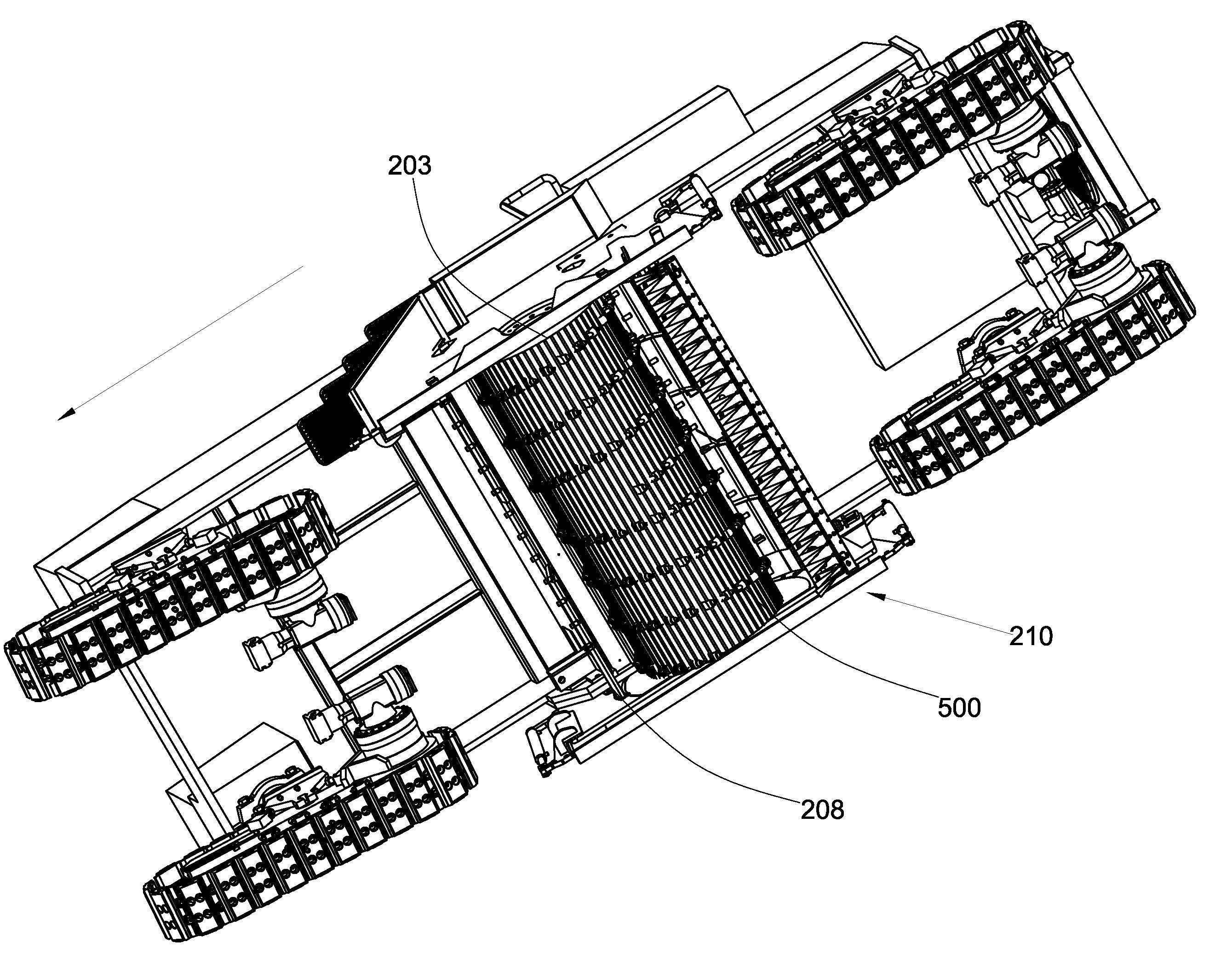
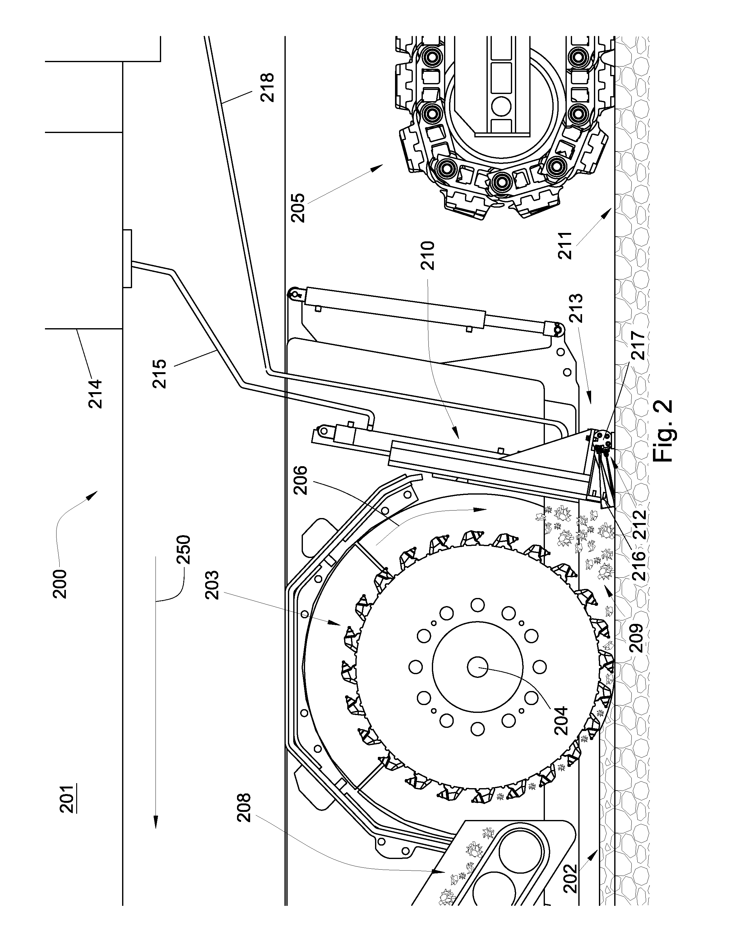
[0022]FIG. 2 is a perspective diagram of an embodiment of the current invention, specifically a system 200 for removing a layer of paved surface. The system 200 may comprise a vehicle 201 adapted to traverse a paved surface 202 in a selected direction depicted by arrow 250 with a milling drum 203 comprising an axle 204 connected to the vehicle 201. In the current embodiment the vehicle 201 comprises tracks, but in other embodiments rubber wheels may be utilized. The milling drum 203 may also be adapted to rotate around the axle 204 substantially normal to the selected direction. In some embodiments the milling drum 203 may be rotated ...


PUM


Abstract

In one aspect of the invention, a system for removing a layer of a paved surface includes a vehicle adapted to traverse a paved surface in a selected direction. A milling drum attached to the vehicle may be adapted to rotate around an axle substantially normal the selected direction of the vehicle. A moldboard may be positioned rearward of the milling drum and also connected to the vehicle. The moldboard may comprise an end that is adapted to push aggregate removed from the paved surface in the selected direction. A plurality of nozzles may be disposed proximate the end of the moldboard which may also be in communication with a fluid reservoir through a fluid pathway.

Description

BACKGROUND OF THE INVENTION[0001]The present invention relates to milling machines that are used in road surface repairs. Milling machines are typically utilized to remove a layer or layers of old or defective road surface in preparation for resurfacing. Resurfacing an existing road surface with such defects may result in a perpetuation of prior existing conditions, especially if the road surface is exposed to heavy and / or continuous traffic which often requires the road to be resurfaced again within a short period of time. Milling may also provide a renewable source of aggregate such as recycled asphalt that may be used to resurface milled surfaces.[0002]Typically the milling machines direct milled road fragments towards a conveyer which takes the fragments off the road, however, a significant amount of debris, aggregate, and fragments remain on the milled surface. When using asphalt or other pavement material to resurface a road the milled surface must be substantially clean of an...

Claims


Application Information

Patent Timeline
Patent Type & Authority Applications(United States)
IPC IPC(8): E01C23/00
CPCE01C2301/50E01C23/088
Inventor HALLWAHIQUIST, DAVIDDUKE, TIMOTHY C.FOX, JOEWILDE, TYSON J.
Owner NOVATEK IP
Why Eureka
Try Eureka