Low voltage microcavity plasma device and addressable arrays

Active Publication Date: 2008-06-05
THE BOARD OF TRUSTEES OF THE UNIV OF ILLINOIS
View PDF35 Cites 24 Cited by
  • Summary
  • Abstract
  • Description
  • Claims
  • Application Information

AI Technical Summary

Benefits of technology

[0013]Microcavity plasma devices and arrays of microcavity plasma devices are provided that have a reduced excitation voltage. A trigger electrode disposed proximate to a microcavity reduces the excitation voltage required between the first and second electrodes to ignite a plasma in the microcavity when gas(es) or vapor(s) (or combinations thereof) are contained within the microca

Problems solved by technology

Early microplasma devices were driven by direct current (DC) voltages and exhibited sh

Method used


Image

  • Low voltage microcavity plasma device and addressable arrays
  • Low voltage microcavity plasma device and addressable arrays
  • Low voltage microcavity plasma device and addressable arrays

Examples


Embodiment Construction

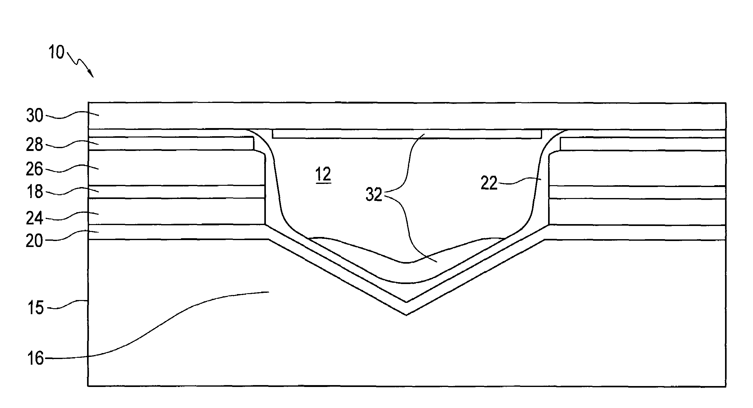
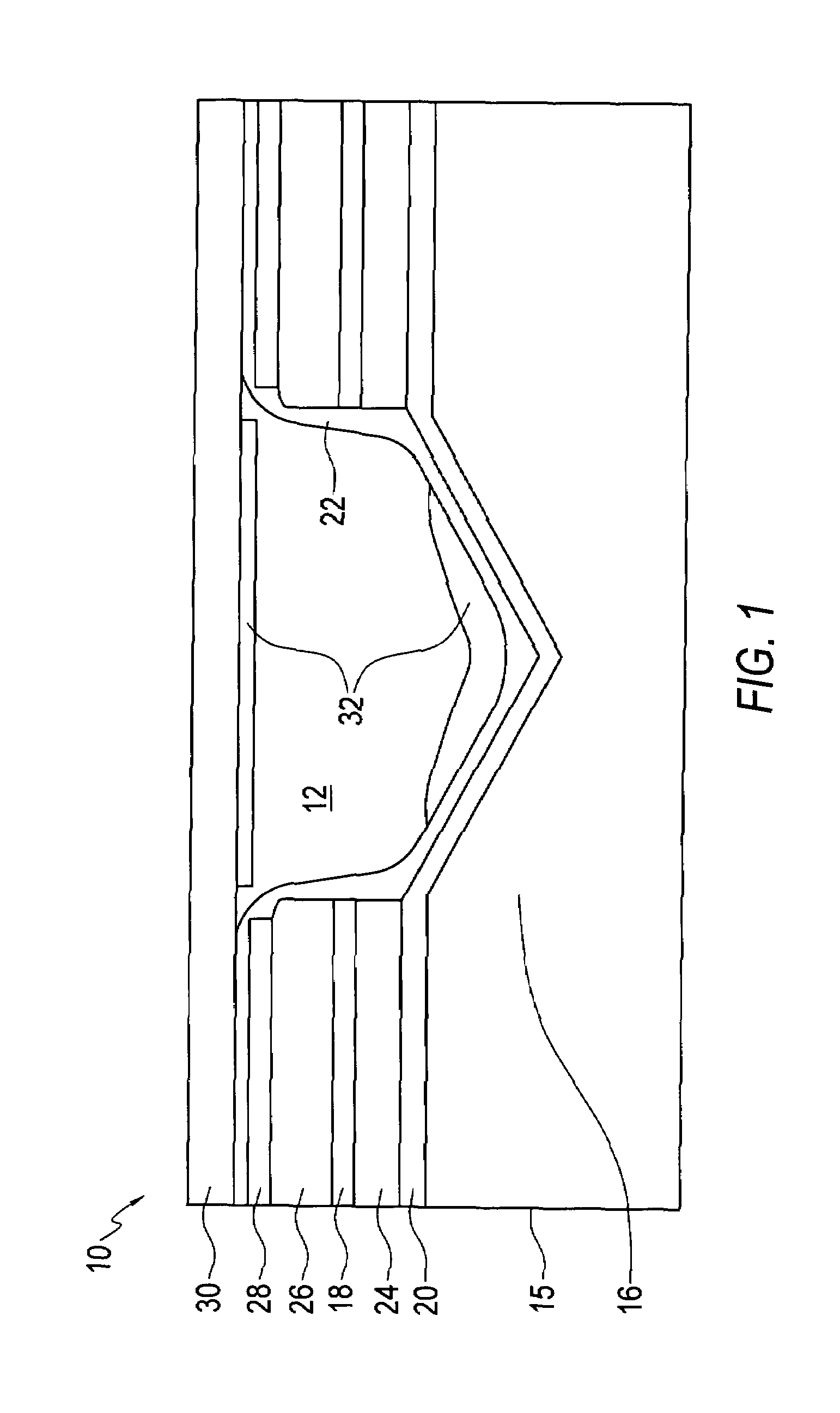
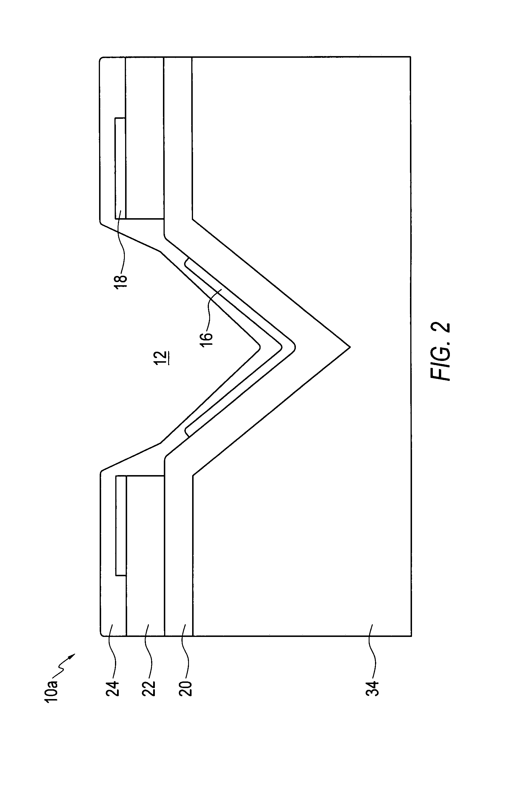
[0031]With this invention, microcavity plasma devices and arrays of microcavity plasma devices are provided that have a reduced excitation voltage relative to previous devices and arrays. A trigger electrode disposed proximate to a microcavity reduces the excitation voltage required between first and second electrodes to ignite a plasma in the microcavity when gas(es) or vapor(s) (or combinations thereof) are contained within the microcavity. Also provided is a symmetrical microplasma device for which current waveforms are the same for each half-cycle of the voltage driving waveform. Additionally, the invention also provides devices that have standoff portions and voids that can reduce cross talk.

[0032]An embodiment of the invention is a microcavity plasma device having a microcavity formed in a substrate. First and second electrodes are disposed to excite a plasma in the microcavity upon application of a time-varying potential (AC, RF, bipolar or pulsed DC, etc.) between the first ...


PUM


Abstract

Microcavity plasma devices and arrays of microcavity plasma devices are provided that have a reduced excitation voltage. A trigger electrode disposed proximate to a microcavity reduce the excitation voltage required between first and second electrodes to ignite a plasma in the microcavity when gas(es) or vapor(s) (or combinations thereof) are contained within the microcavity. The invention also provides symmetrical microplasma devices and arrays of microcavity plasma devices for which current waveforms are the same for each half-cycle of the voltage driving waveform. Additionally, the invention also provides devices that have standoff portions and voids that can reduce cross talk. The devices are preferably also used with a trigger electrode.

Description

REFERENCE TO RELATED APPLICATION AND PRIORITY CLAIM[0001]This application claims priority under 35 U.S.C. §119 from prior co-pending provisional application Ser. No. 60 / 812,755, which was filed on Jun. 12, 2006.STATEMENT OF GOVERNMENT INTEREST[0002]The invention was made with government support under Contract No. F49620-03-1-0391 awarded by the Air Force Office of Scientific Research (AFOSR), and Contract No. NSF DMI 03-28162 awarded by the National Science Foundation (NSF). The government has certain rights in the invention.FIELD OF THE INVENTION[0003]The invention is in the field of microcavity plasma devices, also known as microdischarge devices or plasma devices.BACKGROUND[0004]Microcavity plasma devices produce a nonequilibrium, low temperature plasma within, and essentially confined to, a cavity having a characteristic dimension d below approximately 500 μm. This new class of plasma devices exhibits several properties that differ substantially from those of conventional, macro...

Claims


Application Information

Patent Timeline
IPC IPC(8): H05H1/24F24V30/00
CPCH01J11/12
Inventor EDEN, J.GARYPARK, SUNG-JINTCHERTCHIAN, PAUL A.SUNG, SEUNG HOON
Owner THE BOARD OF TRUSTEES OF THE UNIV OF ILLINOIS
Why Eureka
Try Eureka