Motion and/or scene change detection using color components
a technology of color components and motion detection, applied in the direction of color signal processing circuits, color television details, television systems, etc., can solve the problems of aggravated problems, low noise reduction, and insatiable detection of scene change and motion
- Summary
- Abstract
- Description
- Claims
- Application Information
AI Technical Summary
Benefits of technology
Problems solved by technology
Method used
Image
Examples
first embodiment
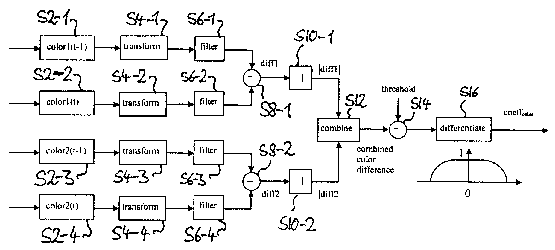
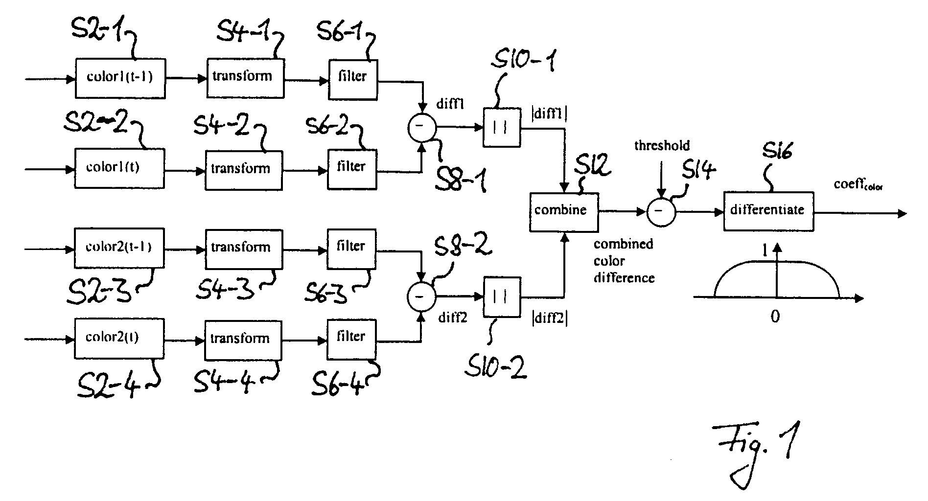
[0019]the present invention is now explained with reference to the schematic block diagram of FIG. 1. All of the following processing is carried out once for every image frame of a sequence and is pixelwise, that is, the following steps are carried out for each pixel of each frame. Application to only some frames of an image sequence and to some pixels of a frame is possible however. The sequence of image frames may for example be given by the sequence of image frames comprised in a video signal or TV signal or by the sequence of images generated by a video camera but is not limited to this. Other non limiting examples are a sequence of image frames obtained by means of X-ray imaging, for example for medical purposes or for imaging or measuring purposes in scientific experiments.
[0020]In the figure, ‘color1’ and ‘color 2’ designates two color components of an image, which, for example, correspond to, but are not limited to, the U and V component of an image represented in the YUV co...
second embodiment
[0031]In the second embodiment a difference value corresponding to the color difference values of steps S8-1 and S8-2 is additionally calculated for the brightness signal. From this brightness difference value the absolute value is taken and is then combined in step S12 with the two other difference values to an overall color difference value. Here again simple addition or the variants of the dE*, including the root of the sums of the squares of the brightness difference value and the color difference values, can be employed for example.
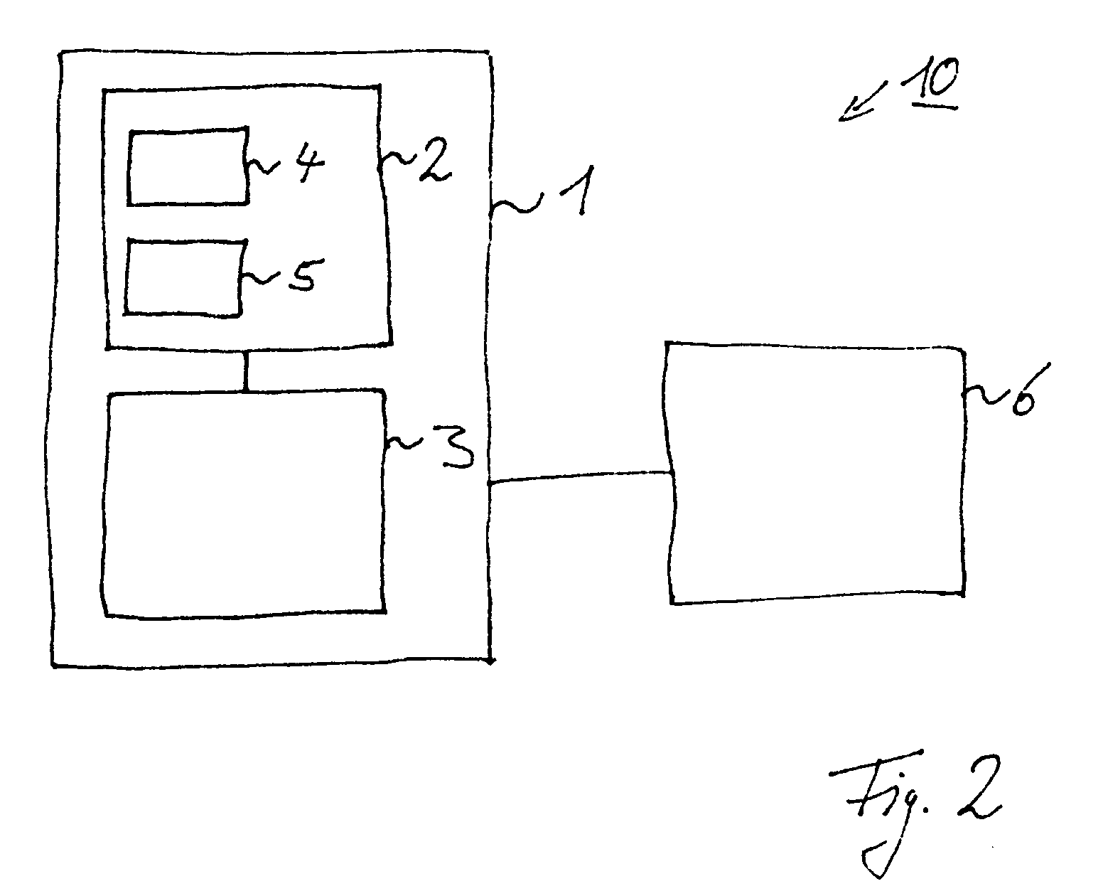
[0032]In a practical implementation of this second embodiment, the difference generator 2 is adapted to calculate the brightness difference value and the absolute value of the brightness difference value and to combine the two color difference values and the brightness difference value to an overall color difference value.
third embodiment
[0033]In the third embodiment a difference value corresponding to the color difference values of steps S8-1 and S8-2 is additionally calculated for the brightness and the overall color difference value obtained in step S12 is weighted with the absolute value of this brightness difference value. This is motivated as follows. If the brightness difference between two temporally neighboring pixels is large, the possibility of motion or scene change is also large. Such brightness difference value is used to weight the overall color difference value between two temporally neighboring pixels. If the brightness difference value is large, the color difference value will be magnified, if the brightness difference is small, the overall color difference value will be attenuated. Thus, in the following differentiation step the decision is biased towards image content or towards noise, respectively. In a similar manner of weighting the color difference value by means of the brightness difference ...
PUM
 Abstract
Description
Claims
Application Information
 - R&D
- Intellectual Property
- Life Sciences
- Materials
- Tech Scout
- Unparalleled Data Quality
- Higher Quality Content
- 60% Fewer Hallucinations
Browse by: Latest US Patents, China's latest patents, Technical Efficacy Thesaurus, Application Domain, Technology Topic, Popular Technical Reports.
© 2025 PatSnap. All rights reserved.Legal|Privacy policy|Modern Slavery Act Transparency Statement|Sitemap|About US| Contact US: help@patsnap.com


