Electrostatically Atomizing Device

a technology of atomizing device and atomizing chamber, which is applied in the direction of corona discharge, instruments, applications, etc., can solve the problem of taking at least several minutes, and achieve the effect of stable operation

Active Publication Date: 2008-06-05
MATSUSHITA ELECTRIC WORKS LTD
View PDF7 Cites 28 Cited by
  • Summary
  • Abstract
  • Description
  • Claims
  • Application Information

AI Technical Summary

Benefits of technology

[0017]Further, the controller may be configured to apply the high voltage across the two electrodes only while the

Problems solved by technology

However, this scheme poses a problem that it will take at least several minutes to obtain the water (co

Method used


Image

  • Electrostatically Atomizing Device
  • Electrostatically Atomizing Device
  • Electrostatically Atomizing Device

Examples


1st embodiment

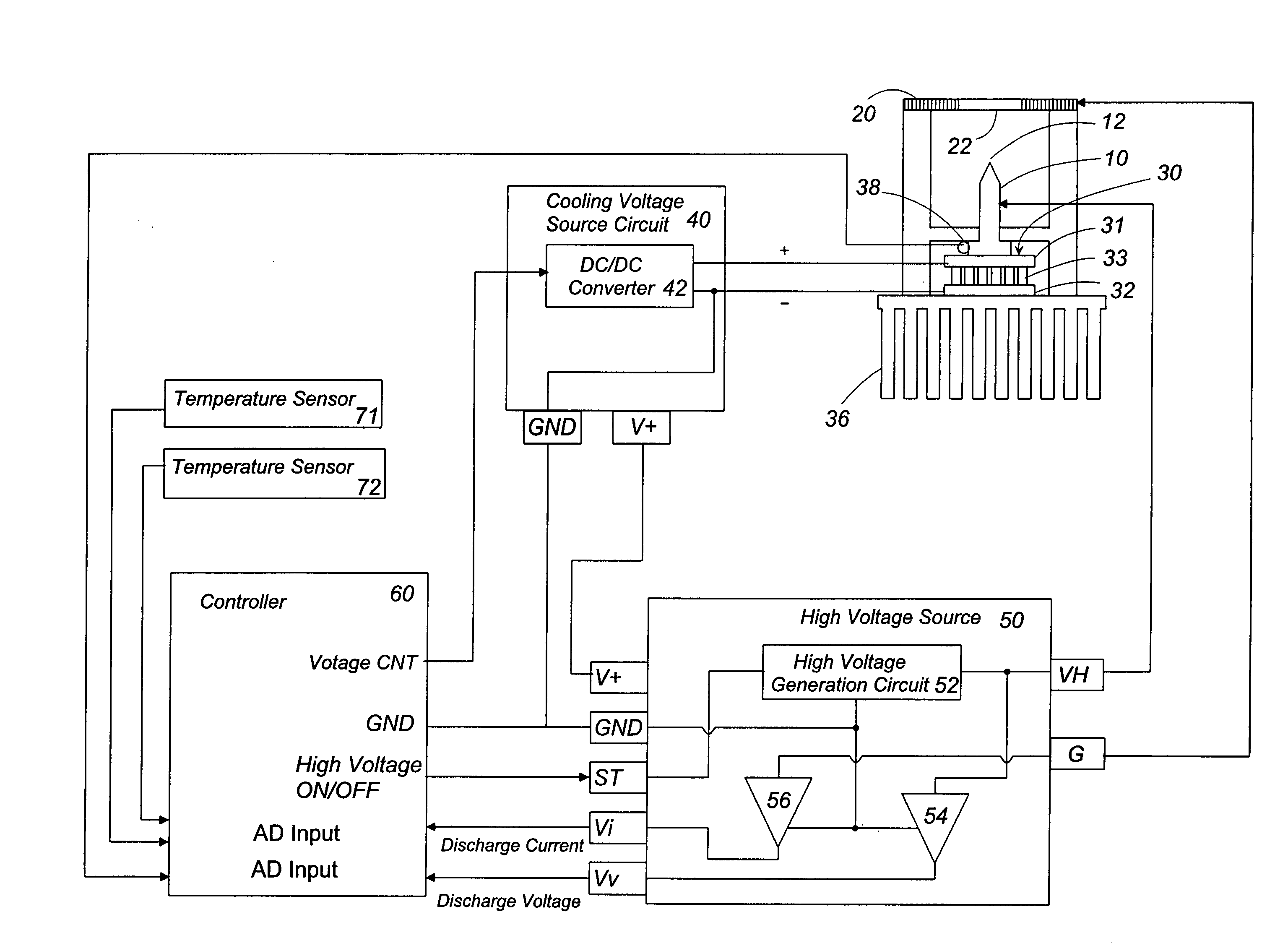
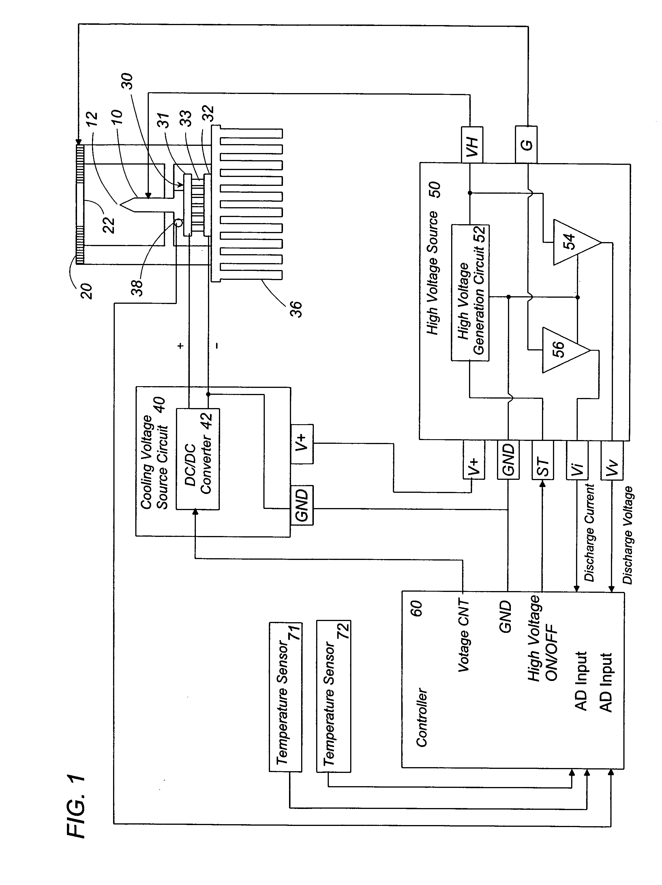
[0028]An electrostatically atomizing device in accordance with the first embodiment of the present invention is explained with reference to the attached drawings. As shown in FIG. 1, the electrostatically atomizing device includes an emitter electrode 10 and an opposed electrode 20 disposed in an opposite relation to said emitter electrode 10. The oppose electrode 10 is shaped from an electrically conductive substrate with a circular opening 22 which has an inner periphery spaced by a predetermined distance from a discharge end 12 at the tip of the emitter electrode 10. The device includes a cooling means 30 which is coupled to the emitter electrode 10 for cooling thereof, and a high voltage source 50. The cooling means is configured to cool the emitter electrode 10 to condense the water content carried in the surrounding air on the emitter electrode 10 to supply the water thereto. The high voltage source 50 is configured to apply a high voltage across the emitter electrode 10 and t...

2nd embodiment

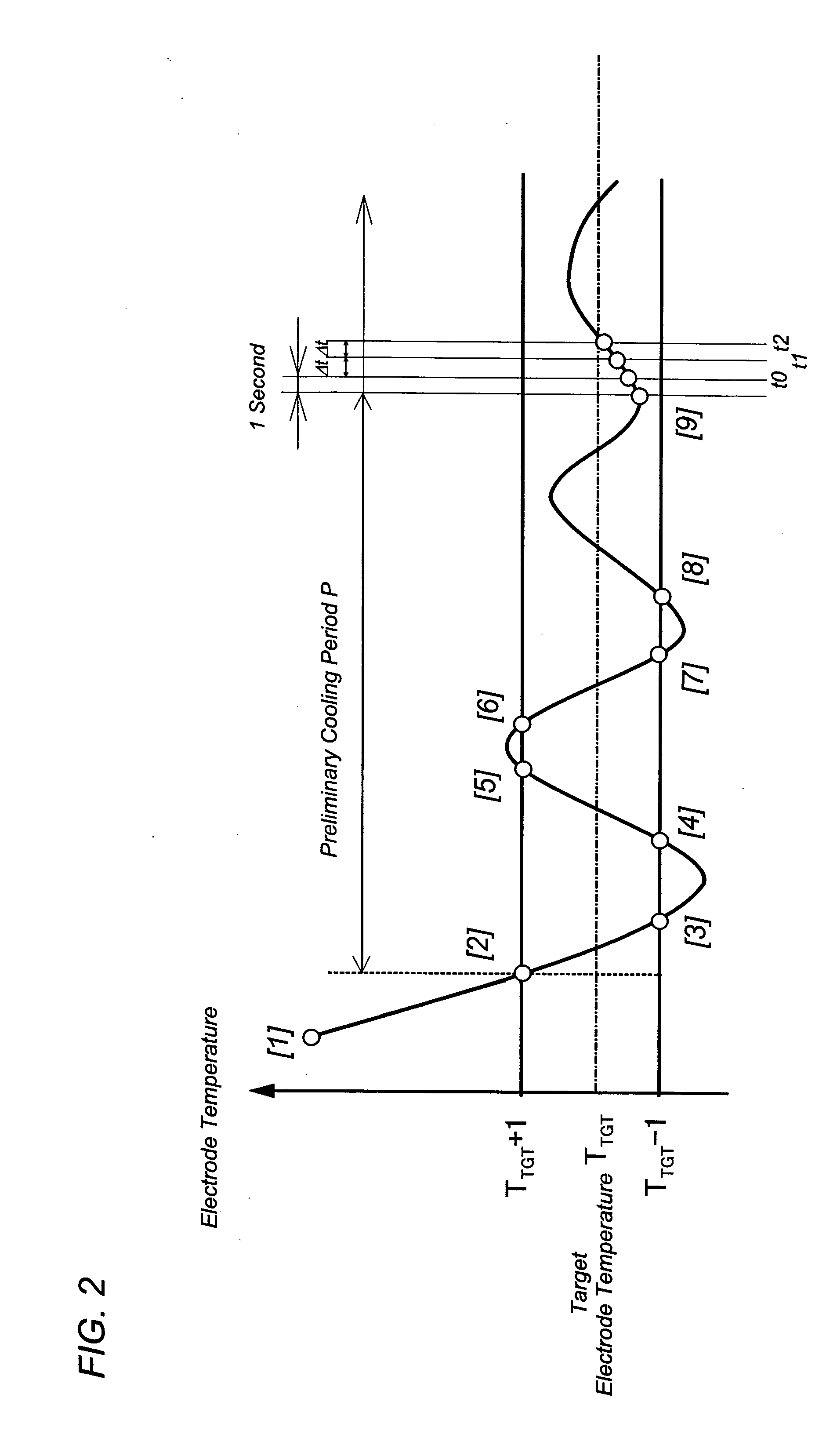
[0058]The electrostatically atomizing device in accordance with the second embodiment of the present invention is basically identical to the first embodiment, except that a different scheme is utilized to adjusting the temperature of the emitter electrode to the target electrode temperature determined on the basis of the environmental temperature and humidity. In contrast to the first embodiment which discloses the PWM control scheme of controlling the Peltier module 30 by means of the duty D which is determined by the temperature difference ΔT between the electrode temperature and the target electrode temperature as seen in Table 2, the present embodiment discloses the control scheme of continuously varying the duty D except at the starting the device so as to cool the emitter electrode to the target electrode temperature determined by the environmental temperature and humidity.

[0059]The controller 60 reads the environmental temperature and humidity so as to obtain the target elect...


PUM


Abstract

An electrostatically atomizing device includes an emitter electrode, an opposed electrode opposed to the emitter electrode, and a cooling means which condenses the water on the emitter electrode from within the surrounding air, and a high voltage source applying a high voltage across the emitter electrode and the opposed electrode to electrostatically charge the water for atomizing charged minute water particles from a discharge end of the emitter electrode. The device further includes a controller for discharging the charged minute water particles in a stable manner. The controller monitors a discharge current flowing between the two electrodes to control the cooling means for keeping the discharge current at a predetermined level, thereby regulating the atomizing amount of the charged minute particles from the emitter electrode.

Description

TECHNICAL FIELD[0001]The present invention relates to an electrostatically atomizing device, and more particularly to the electrostatically atomizing device which condenses water contained in the air and electrostatically charge the condensed water so as to atomize the minute water particles of a nanometer order.BACKGROUND ART[0002]Japanese patent publication No. 5-345156 A discloses a prior art electrostatically atomizing device generating charged minute water particles of a nanometer order (nanometer sized mist). The device is configured to apply a high voltage across an emitter electrode supplied with the water and an opposed electrode to induce Rayleigh disintegration of the water carried on the emitter electrode, thereby atomizing the water. The charged minute water particles thus obtained contain radicals and remain over a long period of time to be diffused into a space in a large amount, thereby being allowed to react effectively with offensive odors adhered to a room wall, c...

Claims


Application Information

Patent Timeline
IPC IPC(8): B05B5/053G05D23/00B05B5/025B05B5/057B05B5/08
CPCB05B5/0255B05B5/057B05B5/0533
Inventor KOBAYASHI, KENTAROYOSHIOKA, HIROKAZUWATANABE, TOMOHARUSUGAWA, AKIHIDEAKISADA, SHOUSUKEHIRAI, TOSHIHISAHIRAI, KISHIKOMIHARA, FUMIOHIRAI, KOUICHIMURASE, SHINYAISAKA, ATSUSHIIMAHORI, OSAMUWADA, SUMIOMATSUMOTO, TATSUHIKO
Owner MATSUSHITA ELECTRIC WORKS LTD
Why Eureka
Try Eureka