Method and apparatus for dynamically allocating bandwidth by hierarchical weight round robin

a hierarchical weight and bandwidth technology, applied in data switching networks, multiplex communication, digital transmission, etc., can solve the problems of essentially occurring transmission delay and increasing overhead, and achieve the effect of minimizing uplink and downlink overhead, reducing overhead, and increasing overall throughpu

Inactive Publication Date: 2008-06-05
ELECTRONICS & TELECOMM RES INST
View PDF7 Cites 12 Cited by
  • Summary
  • Abstract
  • Description
  • Claims
  • Application Information

AI Technical Summary

Benefits of technology

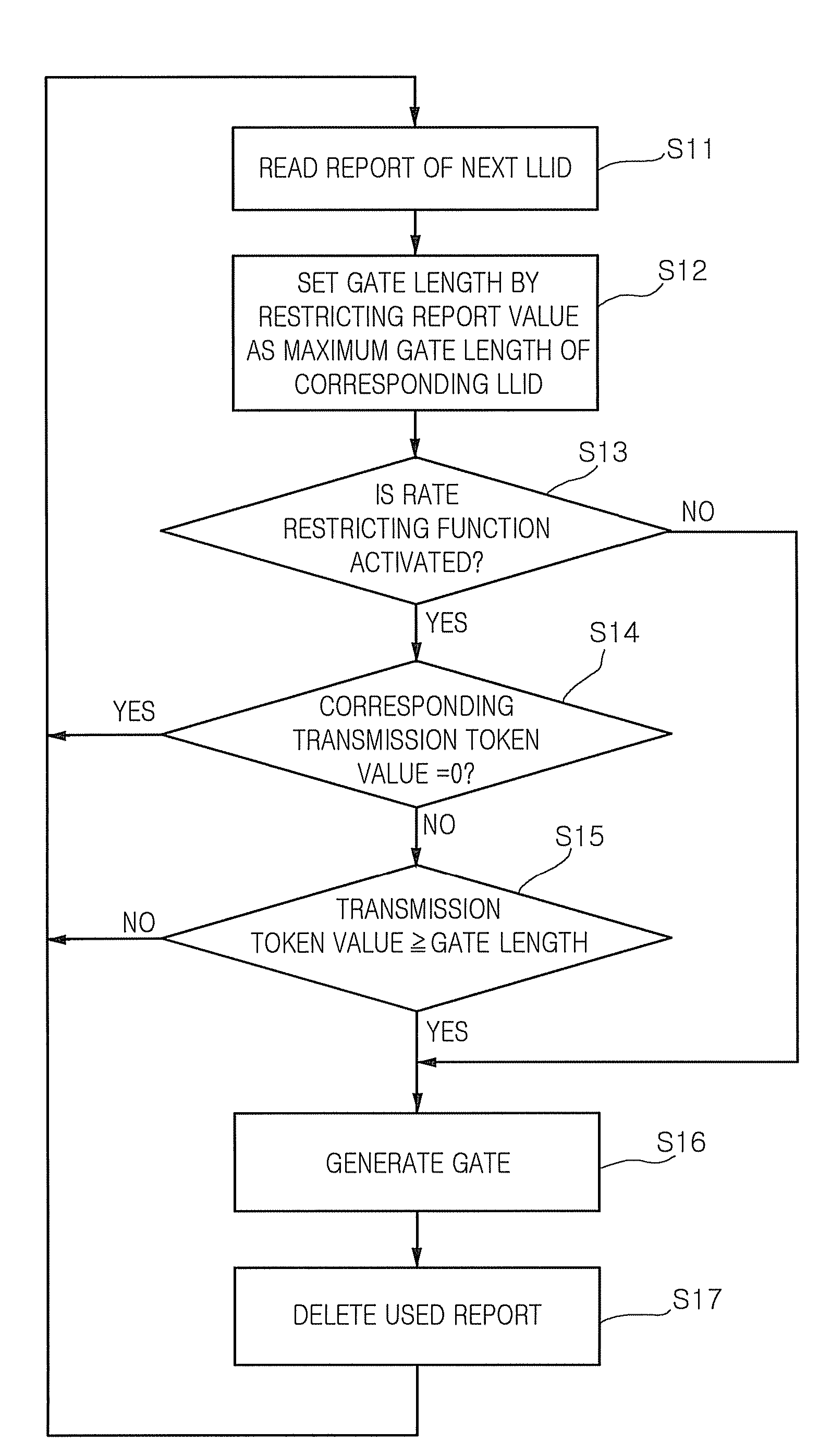
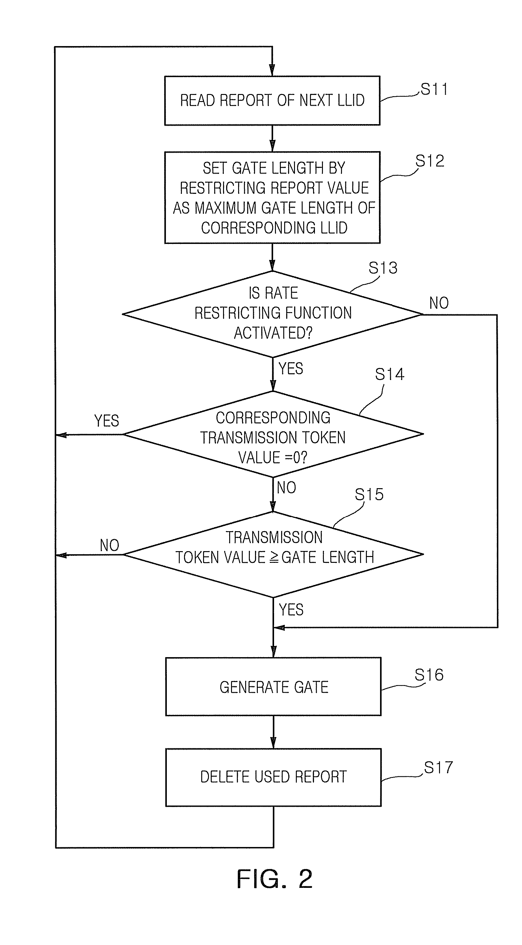
[0023]The dynamic bandwidth allocating method and apparatus according to an embodiment of the present invention sequentially read report values according to LLIDs without a predetermined period, restrict the report values with the maximum gate value set according to a corresponding LLID, and generate the corresponding length of a gate. Therefore, a problem of transmission delay, which is caused by a bandwidth allocating cycle, can be eliminated.
[0024]In the dynamic bandwidth allocation method and apparatus, a report that have been used for generating a gate is removed, a new report is transmitted using the last part of a burst by a gate, a gate transmission is skipped if a report value is 0, generation of a gate is monitored for each LLID, and a gate with fixed length grant is transmitted if a gate has not been generated for a predetermined time. Therefore, the overall throughput increases by minimizing uplink and downlink overhead.
[0025]In the dynamic bandwidth allocation apparatus and method according to present invention, LLIDs are classified into a plurality of classes, and the gate generation is processed by unit of class. The gate generation is controlled based on predetermined values according each class such as a maximum processing time, a maximum allocation amount, a maximum yield processing time, and a maximum yield allocation amount. Therefore, a bandwidth can be effectively allocated.

Problems solved by technology

Due to the delay of the gate, the transmission delay essentially occurs.
In case of regularly performing a bandwidth allocation operation, overhead increases because additional gate is used for collecting the reports.

Method used


Image

  • Method and apparatus for dynamically allocating bandwidth by hierarchical weight round robin
  • Method and apparatus for dynamically allocating bandwidth by hierarchical weight round robin
  • Method and apparatus for dynamically allocating bandwidth by hierarchical weight round robin

Examples


Embodiment Construction

[0035]Exemplary embodiments of the present invention will now be described in detail with reference to the accompanying drawings. The detailed description of well-known functions and elements will be omitted.

[0036]Throughout the accompanying drawings, like reference numerals denote like elements.

[0037]Throughout the specification, if a part is described to be connected to the other part, it means not only that the part is directly connected to the other part but also the part is indirectly connected to the other part with another part interposed therebetween. Also, if a device is described to include a constituent element, it means that the device may further include the other constituent elements as well as the constituent element.

[0038]Each of constitute elements in the present invention is a unit for processing a predetermined function or operation. Each of the constitute elements can be embodied in software, hardware or the combination of software and hardware.

[0039]FIG. 2 is a ...


PUM


Abstract

Provided are method and apparatus for dynamically allocating unlink bandwidth in Ethernet PON. In the method and apparatus, report value, which are received for each logical link identifications (LLID), is controlled to be less than a maximum gate value set for each LLID in sequence for all of LLIDs without a predetermined interval. A gate having a length corresponding to the restricted report value is generated. LLIDs are grouped into classes and processing is done class by class. For each class processing, if maximum processing time is reached or maximum total allocation is reached, the processing is switched to a lower class. Also each class processing, if any higher class has its maximum yield processing time or maximum yield allocated gate reached, the processing is switched to that higher class.

Description

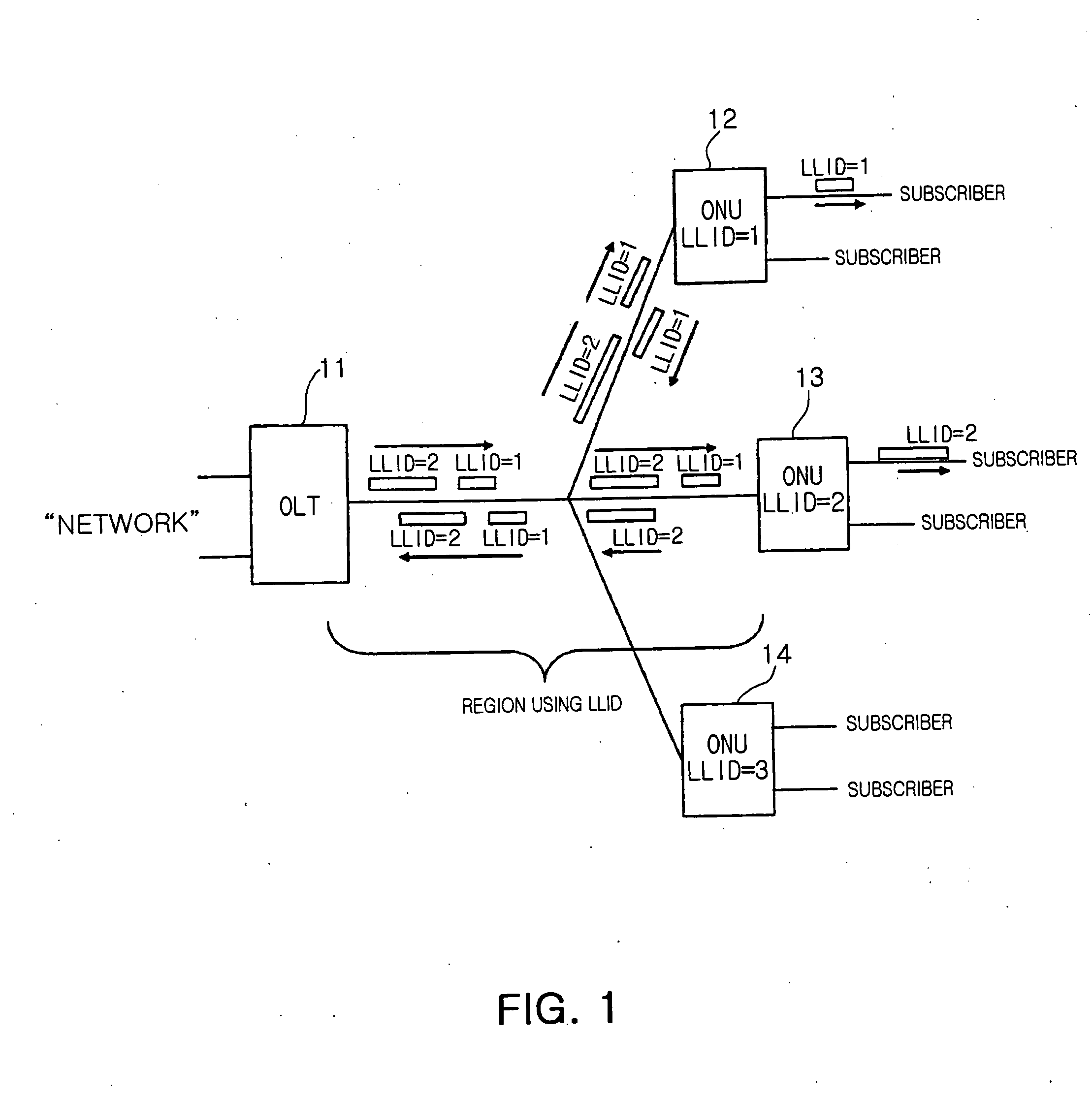
CROSS-REFERENCE TO RELATED APPLICATIONS[0001]This application claims the priority of Korean Patent Application No. 10-2006-120329, filed on Dec. 1, 2006, and the priority of Korean Patent Application No. 10-2007-71022, Jul. 16, 2007, in the Korean Intellectual Property Office, the disclosure of which is incorporated herein by reference.BACKGROUND OF THE INVENTION[0002]1. Field of the Invention[0003]The present invention relates to a method and apparatus for dynamically allocating uplink bandwidth for transmitting frames from an optical network unit (ONU) to an OLT in an Ethernet passive optical network (EPON).[0004]The present invention was supported by the IT R&D program of MIC / IITA. [2005-S-401-02, Project title: High Speed Optical Network Technology].[0005]2. Description of the Related Art[0006]In an EPON, one of optical network technologies, an OLT located at a network side is connected to a plurality of optical network units (ONUs) or optical network terminals (ONTs) located at...

Claims


Application Information

Patent Timeline
Patent Type & Authority Applications(United States)
IPC IPC(8): H04L12/56
CPCH04Q11/0067H04Q2011/0084H04Q2011/0064
Inventor KIM, CHANYOO, TAE WHANKIM, BONG TAE
Owner ELECTRONICS & TELECOMM RES INST
Why Eureka
Try Eureka