
System and method for laser temperature compensation

a laser temperature compensation and temperature compensation technology, applied in the direction of lasers, semiconductor lasers, electric discharge lamps, etc., can solve the problems of inconvenient direct monitoring of optical power or wavelength, difficult or even impossible to achieve proximity, inaccurate,

Inactive Publication Date: 2008-06-05
FINESSE SOLUTIONS
View PDF3 Cites 16 Cited by
  • Summary
  • Abstract
  • Description
  • Claims
  • Application Information

AI Technical Summary

Problems solved by technology

Such proximity is often difficult or even impossible to achieve for small optical devices that are often pre-packaged.
This method has relatively limited utility since it requires that both the thermistor properties and the optical source power variation with temperature be known.
However, directly monitoring the optical power or wavelength is often inconvenient, inaccurate, or both.
Additionally, separate thermistors or similar temperature sensitive devices may be difficult or impractical to mount sufficiently proximate to the optical power source to provide an accurate reading of the source temperature.
These facts, in conjunction with the fact that using a thermoelectric cooler is often impractical, leads to the need to sense the temperature of the optical source without requiring a separate sensor.

Method used


Image

  • System and method for laser temperature compensation
  • System and method for laser temperature compensation
  • System and method for laser temperature compensation

Examples


Embodiment Construction

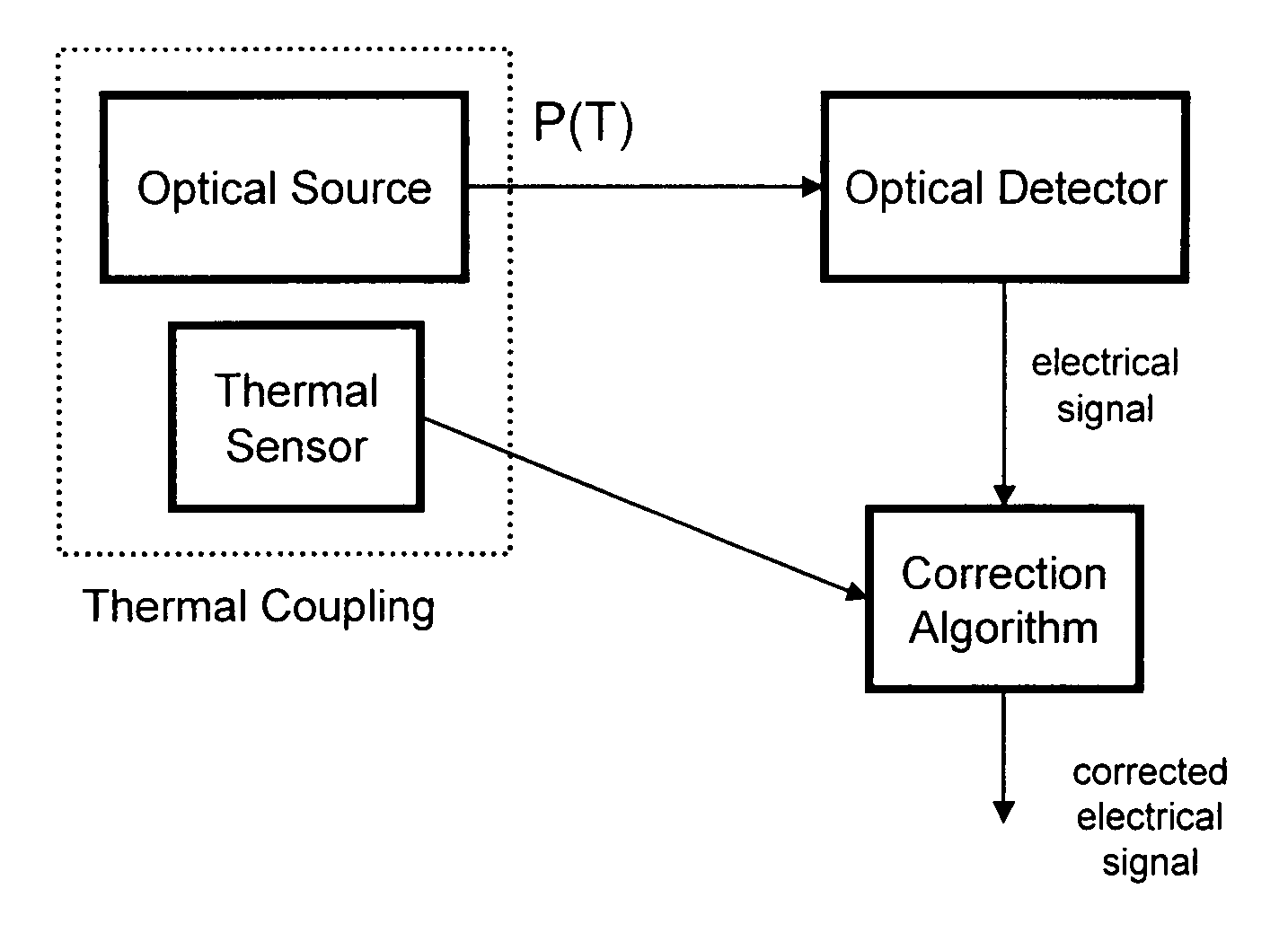
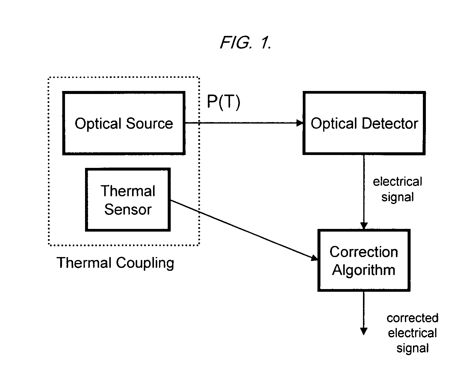
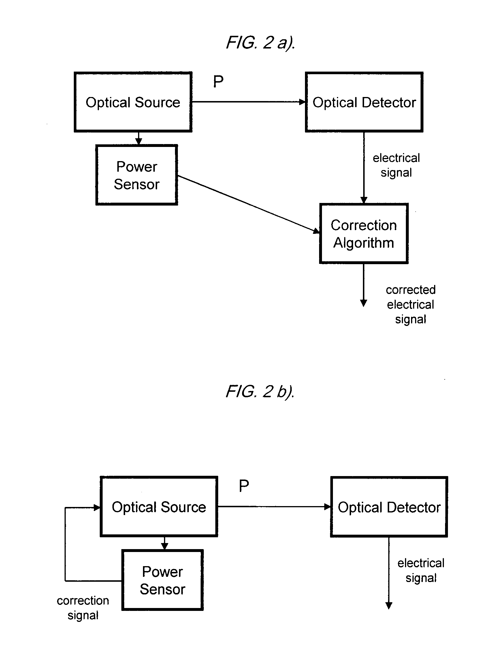
[0034]As shown in FIG. 6, the optical semiconductor device, i.e. the laser or LED optical source is driven by an input signal, (normally current); and produces an output power PS which is primarily a function of the input signal and the ambient temperature (S,T). As the optical power travels through an optically dense sample medium the transmitted power, as measured by a photodetector, is affected by one or more mechanisms such as absorption, scattering, and / or reflection in the sample medium. The result is a power at the detector, Pd which is less than, or (in the absence of absorption, scattering or reflection) equal to the source power. An “absorbance unit” may be associated with the sample medium defined by “optical loss” or “optical density” such that the “absorbance unit” or AU is given by log10(PS / Pd).

[0035]The present invention uses the optical semiconductor device itself as a temperature sensor, as shown in FIG. 7. This approach ensures that the temperature of the optical d...


PUM


Abstract

A method for compensating for changes in output power or wavelength of an optical source with temperature. Many optical sources have power and / or wavelength variations with temperature which can be compensated by open- or closed-loop methods if a method of accurately measuring the optical source temperature is available. The voltage across a semiconductor junction varies with temperature. Measuring the optical source power or wavelength variation with temperature and tracking the voltage across the semiconductor junction provides a means for compensating an instrument for temperature induced optical output power or wavelength variations. An important field of application is optical density or turbidity measurements in cellular media.

Description

CROSS REFERENCE TO RELATED APPLICATIONS[0001]This application claims priority from co-pending, provisional application Ser. No. 60 / 872,749, filed Dec. 4, 2006.FIELD OF THE INVENTION[0002]The present invention relates generally to the field of solid state optical source (i.e., laser or LED) temperature compensation.BACKGROUND OF THE INVENTION[0003]Many optical instruments and devices require a known optical power or wavelength output which remains relatively constant even if the ambient temperature of the instrument changes. When optical sources have variations related to changes in the source temperature, then some method of monitoring the source optical power, wavelength, and / or temperature must be provided in order to maintain a desired optical power and / or wavelength output or to predict the optical output. For many optical sources the output power and / or output wavelength will vary with the source temperature. These variations can be compensated for by open- or closed-loop metho...

Claims


Application Information

Patent Timeline
IPC IPC(8): H01J7/00H01S3/00
CPCH01S5/024H01S5/06808H01S5/02415
Inventor RIDDLE, ALFREDHAVARD, JOHN
Owner FINESSE SOLUTIONS
Learn More